


ML-x17 DATA LOGGER MANUAL
Manufacturers of low power instruments
page 46
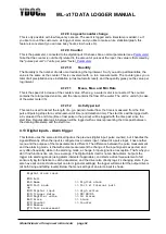
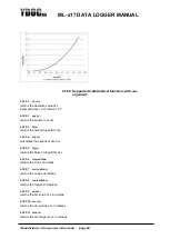
4.17 Aggregation Channels
The logger is equipped with 8 aggregation channels which can be used to record aggregated values
(average, minimum, maximum, gust and standard deviation) calculated over a period of your choosing.
The number of samples taken into account during the aggregation period is depending on the period
duration and the
‘Sample interval’ as configured for the used input parameter/sensor.
Each channel has an aggregation buffer of 600 values. So, a 10-minute aggregation period (600
seconds) can be sampled with 1Hz, longer aggregation periods e.g. 20 minutes can be sampled with 1Hz
but will cause the use of intermediate averages. As 1Hz is the highest possible aggregation sample rate,
shorter aggregation periods will contain less samples (e.g. 120 samples for a 2-minute aggregation
interval). An aggregation interval can be shorter or longer than a data log interval, so it’s possible to
record a 10 minute (rolling) average every 2 minutes. Or record the last 2-minute average every 10
minutes.
With a 1Hz sample rate the logger needs to wake-up and take a sample every second, to avoid draining
the batteries the used sensors should require a short warm-up (a fraction of the sample interval) consume
as little power as possible preferable none (like a reed switch based anemometer), self-powered (like a
pyranometer) or negligible (like a 20KOhm wind vane potentiometer). The power draw is about reversed
proportional to the sample interval, a twice longer interval will draw about 50% less power.
Per aggregation channel you have to choose
which input/sensor values you want to use for
aggregation.
For input type you can choose ‘Scalar’,
‘Direction’ or ‘dB’.
A normal ‘Scalar’ value like a windspeed can
be averaged by accumulation and division. A
direction (0..360 deg) like wind direction
needs to be dissolved in two x and y components first and their average combined back into a direction
again.
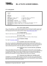
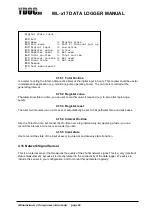
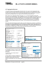
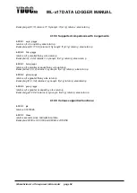
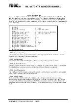
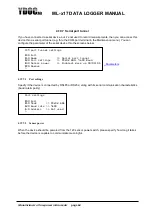
Configuration setup
[0] Exit
[1] General settings >> YDOC6721BK
[2] Modem
settings
[3] NTP time update >> Used
[4] Alarm SMS >> Not
used
[5] Option boards >> Not used
[6] Internal sensors >> Internal
[7] Analog sensors >>
Potentiometer
[8] Digital sensors >> Digital pulse
[9] Network signal sensor >> Not used
[A] Serial port >> Not
used
[B] Accessory port >> Not used
[C] Derived channels >> Used
[D] DTU connection >> Not
used
[E] Email output >> Not used
[F] FTP output >> Not
used
[G] TCP output >> TCP
[-] HTTP output >> N/A
>
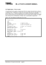
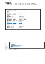
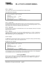
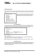
Derived channels
[0] Exit
[1] Aggregations >> Used
[2] Calculations >> Not used
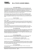
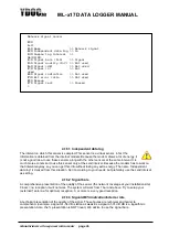
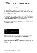
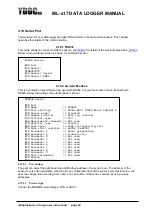
Aggregation channel 1
[0]
Exit
[1] Input parameter >>
Direction (D)
[2] Input type >>
Direction
[3] Aggregation period >>
00:10:00
[4] Average >>
Average Direction
[5] Minimum >>
Minimum
Direction
[6] Maximum >>
Maximum Direction
[7] Gust >> Not used
[8] Deviation >>
Deviation
[9] Percentage of Change >> Not used
[A] Rate of Change (unit/h) >> Not used
[B] Percentile 1 >> Not used
[C] Percentile 2 >> Not used
[D] Percentile 3 >> Not used
[R] Remove
>


