background image


EtherAnt II User’s Manual 


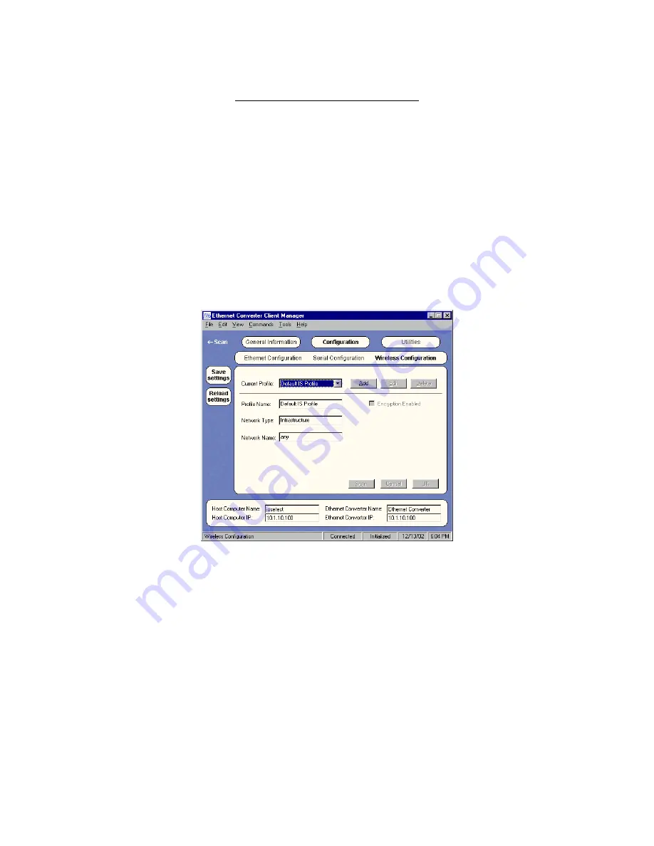
Wireless Configuration (Figure 3.11) 

Current Profile – 

This field allows you to select the profile name that identifies the settings for your 

network.  You can add, edit, or delete profiles. A profile is a combination of settings that you can define 
and then use over and over. 
 

Profile Name – 

This field represents an arbitrary identifier for each configuration profile you create (up to 

32 characters).  The value in this field is for convenience in identifying multiple configuration profiles in the 
Client Manager.  You should use a descriptive name that has relevance to your particular network 
environment.  Up to 1000 profiles may be stored within the Client Manager database.  This database is 
preserved when the Client Manager is upgraded. 
 

Network Type –

 This field allows you to select the type of network that you will be connecting to.  The 

options from the drop-down menu are:  Infrastructure if you are connecting to an Access Point, Peer-to-
Peer if you are setting up an Ad Hoc group, or Wireless Link if you are setting up a wireless (bridged) 
network.

 Note: 

Wireless Link mode disables Micro-routing. 

Figure 3.11 – Wireless Configuration 


Network Name – 

This field allows you to enter the Network Name


(or Extended Service Set Identifier, 

ESSID) that is set in your AP or the one that you will use to establish an Ad Hoc group.  The Network 
Name is used to specify a unique IEEE 802.11 wireless network.  Wireless stations use the Network 
Name to associate.  Only devices with the same Network Name will associate with each other.  
Alphanumeric values may be used in this field (up to 32 characters).  A Network Name of 

Any 

may be 

used in Infrastructure mode to associate with “any” open AP. 
 

Channel ID –

 This field allows you to set the Channel to use for wireless communication.  This field only 

applies to Peer-to-Peer and Wireless Link modes.  When in Infrastructure mode, the EC will automatically 
scan each channel for the AP. 
 

Partner Name –

 This field allows you to specify which EC you will be creating a wireless link with.  This 

field only applies to Wireless Link mode. 
 

Version 3.3 

Page 16 

March 2003 

Содержание EtherAnt II

Страница 1: ...Version 3 3 March 2003 ...

Страница 2: ... any of the following occurs 1 The product enclosure is opened 2 The antenna connections are not properly waterproofed 3 The device is installed improperly or with incorrect connectors 4 The round connector of the outdoor Ethernet cable provided is improperly plugged into the rear jack of the antenna 5 The antenna or DC Power Injector are physically damaged 6 The device is operated outside the rec...

Страница 3: ...lation 6 Section 3 The Client Manager 8 3 1 Installation 8 3 2 Using the Client Manager 9 3 3 General Information 10 3 4 Configuration 15 3 5 Utilities 18 3 6 Removing the Program 21 Appendix A Frequently Asked Questions FAQs 22 2003 Young Design Inc All Rights Reserved No part or parts of this document may be reproduced translated stored in any electronic retrieval system or transmitted in any fo...

Страница 4: ...automatically routes IP packets for up to 253 MAC addresses on the LAN no special configuration is necessary The Micro routing algorithm maintains an auto indexed IP to MAC address table by inspecting each received 802 3 Ethernet frame Thereafter the EtherAnt s local MAC address is superimposed as the source address field within the frame prior to transmitting it on the wireless 802 11b network Re...

Страница 5: ... gain and 15 beamwidth Transmit power of 2 Watts EIRP and 16 Watts EIRP on LR model Up to 4 5 Mbps actual throughput FCC Part 15 Certified for license free operation 11 channels in USA Professional installation is not required by FCC Part 15 rules Easy to run outdoor rated Ethernet cable provided 50 feet standard can be optionally extended up to 300 feet for standard series and up to 100 feet for ...

Страница 6: ...mast tilt bracket mount Outdoor Ethernet cable with weatherproof antenna connector 50 feet standard can be optionally extended up to 300 feet for standard series and up to 100 feet for LR models Cat 5 DC Power Injector DC Power Adapter for 110 VAC 220 VAC optional output 15 VDC LR model comes standard with a 110 220 VAC laptop type adapter output 15 VDC CD ROM with Client Manager software and docu...

Страница 7: ...t prior to deploying it in the field Set up a mini network that resembles your actual configuration as close as possible By using such a mock up troubleshooting potential problems will be much easier than if you already installed the equipment in the field Read through this entire Section 2 to understand how to install the hardware To configure the EtherAnt II read Section 3 2 2 Mounting the Ether...

Страница 8: ...ntenna is aimed at a vertically polarized omni directional or sector base station antenna it must be mounted vertically polarized using the other mounting stud on the back Figure 2 1 Outdoor Pole Mount Installation Figure 2 2 shows the antenna in a typical indoor wall mount installation For indoor applications the range will depend on the walls and other obstacles between the EtherAnt II and the b...

Страница 9: ...ced Link Test screen of the Wireless Client Manager program shows signal strength levels Walk around the desired coverage areas with the laptop computer and record the signal levels This way you can build a map of the areas that have good coverage For details about how to set up configure and use the Wireless Client Manager program please refer to the User Manual of the product 2 6 Hardware Instal...

Страница 10: ...wer Injector 6 Check that the Power and Ethernet LEDs are lit For LR models check that the RX Power amplifier LED green is also lit 7 Configure the EtherAnt II Client Adapter using the Client Manager software See Section 3 for detailed information Figure 2 3 Plugging the Outdoor Ethernet Cable Figure 2 4 shows the EtherAnt II label located on the back of the flat panel Six green LEDs appear to the...

Страница 11: ...n the contents of the CD ROM drive and select the following directory Management YDI Client Manager Run the Set Up program 2 The Splash screen will appear first Choose Next to continue the installation or Cancel to terminate 3 The Welcome screen will appear Choose Next to continue the installation or Cancel to terminate 4 The License Agreement screen will appear Read the Agreement and click on I a...

Страница 12: ...other user will be given access to that EC Once the logged in user logs out the status will then reflect whether it is online or offline Figure 3 1 Select EC Screen A number of other functions can be performed using the buttons found at the bottom of the screen as described below Clear List This command will clear all ECs from the list The program will automatically start scanning for devices agai...

Страница 13: ...Pressing this button will restore the parameters that are currently saved in the attached EC General Information This screen automatically displays information about the connection with the device you selected The Status Bar on the bottom of the window should indicate Connected if you have a connection If the Status Bar reads Not Connected then you are not connected with the device Other informati...

Страница 14: ...isplays the IP address of the computer you are using Ethernet Converter Name This read only property displays the name of the EC you are currently connected to Ethernet Converter IP This read only property displays the IP address of the EC you are currently connected to Converter Manager Tool Bar Located at the top of every screen is the Converter Manager Tool Bar Described below are the commands ...

Страница 15: ...AC Address of the most recently received Ethernet frame from the Ethernet port will be used Note this setting disables Micro routing If Use EC MAC Address is clicked the internal MAC Address of the unit will be used this is the default setting Note this setting automatically enables Micro routing in Infrastructure and Peer to Peer modes If Use PC Card MAC Address is clicked the internal MAC Addres...

Страница 16: ... Antenna Selection This option only available for the Design In model allows the user to select which antenna port on the 802 11 b PCMCIA Card to use Figure 3 5 Options Ethernet Figure 3 6 Options PC Card Options Serial Figure 3 7 NOTE Although there is a tab for Serial port settings the EtherAnt does not use a serial interface All screens for Serial settings should be ignored since they are not a...

Страница 17: ... designed to help you configure one or two ECs from the default configuration to the configuration that matches your needs This includes the wireless and Ethernet settings Serial Configuration Wizard Although there is a Wizard for Serial configuration the EtherAnt does not use a serial interface All screens for Serial settings should be ignored since they are not applicable The Client Manager gray...

Страница 18: ...on Gateway This field sets the IP Address of the Gateway router or firewall You will need to enter the IP address of your gateway particularly if you plan to use the EC to access computers or other EtherAnt II units beyond your router or firewall MAC Address This read only property displays the MAC Address of the EC you are currently connected to Automatically Search for Unknown Ethernet Addresses...

Страница 19: ...nt Peer to Peer if you are setting up an Ad Hoc group or Wireless Link if you are setting up a wireless bridged network Note Wireless Link mode disables Micro routing Figure 3 11 Wireless Configuration Network Name This field allows you to enter the Network Name or Extended Service Set Identifier ESSID that is set in your AP or the one that you will use to establish an Ad Hoc group The Network Nam...

Страница 20: ... key see Figure 3 13 Use Key This field allows you to choose which key to use for encryption Encryption Type This field allows you to specify whether to use a 64 bit or a 128 bit encryption key For a 128 bit encryption key use a 26 character hex key or a 13 character alphanumeric key For 64 bit encryption key use a 10 character hex key or a 5 character alphanumeric key Encryption Formats The two f...

Страница 21: ...ient Manager installed because the settings are stored in the non volatile memory of the EtherAnt II 3 5 Utilities Diagnostic Utility Figure 3 14 The Diagnostic Utility Screen is invaluable for checking the reliability of the radio link If you are associated with an YDI or ORiNOCO compatible WLAN card in an Access Point or EC you will also see the signal levels of your Partner typically the Access...

Страница 22: ...ackets are received the diagnostic utility screen will update the number of successfully received packets at each specified rate These signal levels are also very useful for aiming the antenna Adjust the aim such that you get the best signal strength with the highest possible SNR The signal levels appear as horizontal bars that change colors depending on the strength of your signal Green means an ...

Страница 23: ...rocess fails the CM displays a warning message clearly stating that the update has failed The user should then attempt to log back in via the CM and re run the update process After the process is done and verified the CM will issue a reset command to the EC that will cause the new program image to be loaded into RAM and return to the Select EC Screen The Firmware Image File should reflect the late...

Страница 24: ...ou through this process The latest firmware can be found at www ydi com support downloads php Firmware and Client Manager software are distributed together to ensure synchronized capability and features for smoother operation 3 6 Removing the Program Prior to installing a newer version of the Client Manager program you will need to remove any older versions Follow these steps 1 Under the Start but...

Страница 25: ... only be fixed at our facilities 3 Why can I not log on Client Manager Only one Client Manager Login is allowed at a time The Client Manager will not allow two users to log on simultaneously 4 Why does my EC seem to reduce its transfer speed sometimes Transfer Speed is reduced with Client Manager login approx 25 You should not leave the Client Manager logged in continually The Client Manager was d...

Страница 26: ...er needs to be set to the default value of Large meaning there are not many APs covering the area This keeps client devices from easily wandering off looking for other APs if there is any kind of transient interference The settings Medium or Small distance between access points require an excellent quality of radio communications throughout the entire wireless coverage area In environments where t...

Страница 27: ...EtherAnt II User s Manual Version 3 3 Page 24 March 2003 ...

Страница 28: ......

Отзывы: