4.
Control parameter setting
4.1.
Boot information
full screen >>> XMTN
(
N shows the quantity of zones
)
>>> V3.00
(
Software version
number
)
>>> normal condition
4.2.
CHANNEL SELECT
After long press or for one second, the current loop number starts flashing, and then
short press or to switch the control loop. The N+1 channel is the temperature display
of the environment (cold end of thermocouple).
4.3.
Control parameter setting
Long press for 3 seconds to enter the setting state of control parameters. At this time,
the upper row displays parameter prompt SV, and the lower row displays control parameters.
At this point, the single digit flashes, short press and move the flshing digits. After
selecting the number of digits to be modified, short press or to modify the control
parameter. Continue to press , and display each parameter prompt in the upper row. After
finding the parameter that needs to be modified, continue to press to move the flshing
digits. After selecting the number that needs to be modified, press or again to modify
the control parameter.
Long press for more than 1 second, the controller automatically returns to the normal
control state (no button operation within 60 seconds, the controller automatically returns to the
normal control state).
4.4.
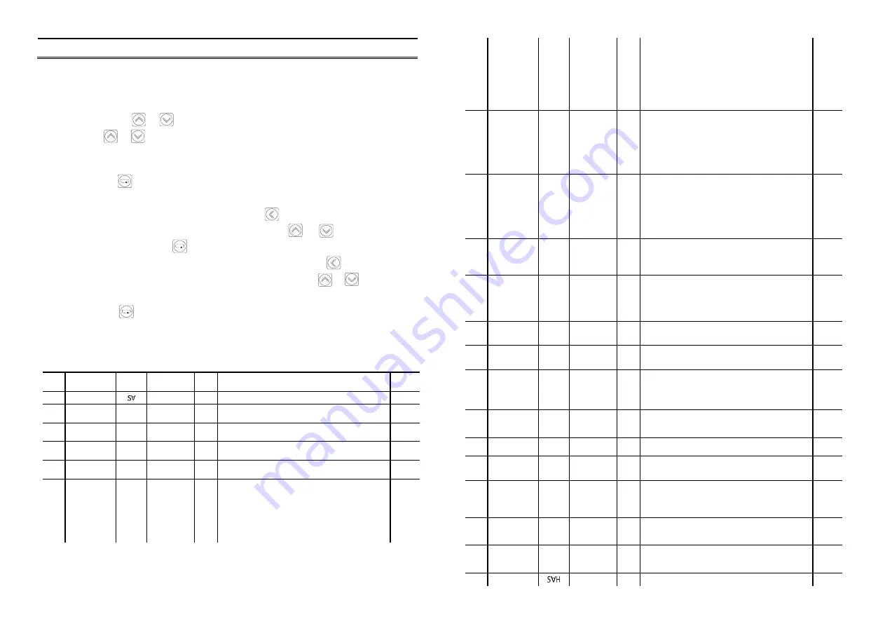
A list of control parameter Settings
No.
Parameter
Name
Symbol Data Range Unit
Introductions
Initial
value
1
Set value
SVL
~
SVH
℃
The set target value of the zone of the controller
100
2
The lower
limit alarm 1
AL1
-500
~
4000
℃
See 4.5, alarm output instructions for details
50
3
The lower
limit alarm 2
AL2
-500
~
4000
℃
Same as AL1, but can only be output through
communication
50
4
Upper limit
alarm 1
AH1
-500
~
4000
℃
See 4.5, alarm output instructions for details
50
5
Upper limit
alarm 2
AH2
-500
~
4000
℃
Same as AH1, but can only be output through
communication
50
6
Alarm type
SA
00
~
66
—
The single digit of XX is type 1 of alarm, while the
ten digit is type 2 of alarm. X=0: no alarm; 1: upper
limit deviation alarm; 2: lower limit deviation alarm;
3: alarm outside the deviation value of upper and
lower limits; 4: alarm within the deviation value of
upper and lower limits; 5: upper absolute value
alarm;
01
7
Positive and
negative
action control
and first
power on
alarm enable
EA
000
~
111
—
The hundred digits of XXX are positive and
negative control options: X=0: reaction control
(heating type); 1: positive action control (cooling
type). The ten digit of XXX is first choice of alarm
2, the single digit of XXX is first choice of alarm 1:
X=0: After the power on the alarm condition does
not alarm, then all alarm if the alarm condition is
met; 1: all alarm if the alarm condition is met.
011
8
Proportional
band
P
0
~
9999
℃
Regulation of proportional action: the larger the P,
the smaller the proportional action, the lower the
system gain. 0: change to on-off control mode. At
this point, the integral time I becomes 0.1 times of
the upper limit of the insensitive region and the
differential time D becomes 0.1 times of the lower
limit of the insensitive region.
30
9
Integral time
I
0
~
9999
Sec.
Integral action time constant: the larger the I, the
weaker the integral action, mainly used to eliminate
the static difference. 0: become a PD control
method, the integral inhibit Ar to set (RESET), and
the Ar is set to zero, the unit for
, is used to
℃
eliminate static error. When P=0, see the description
of P.
240
10
Differential
Time
d
0
~
9999
Sec.
Differential action time constant: the larger the D,
the stronger the differential action, which is mainly
used to restrain the overshoot of measured values.
When P=0, see the description of P.
60
11
Restrained
Integration
Ar
0
~
100
%
Restrained Integration ratio: the larger the Ar, the
larger the overthrust, and the smaller the Ar, the
possible static difference.
When the integral time I is equal to 0, see the
description of the integral time I
100
12
Control cycle
t
1
~
100
Sec.
Output of thyristor or solid-state relay: 2~3 seconds;
Relay output: 20~30 seconds
3
13
Sensor error
correction
Pb
-500
~
4000
℃
Used to correct measurement error caused by sensor
and thermocouple compensation wire
0.0
14
Auto tuning
At
n
O or YES
—
YES: start self-tuning and restore nO after
self-tuning. If the self-tuning rule is not completed
within 4 hours, the original P, I and D values are still
used for control.
n
O
15
Auto tuning
Limit
AtU
0
~
100
%
In order to overcome the overshoot phenomenon of
the Auto tuning time, the Auto tuning control point
can be lowered to SV x ATU.
100
16
Graduation
S
n
0
~
18
—
See 1.2 list of commonly used input types and range
for details.
3-K
17
Decimal
point
dP
0
~
1
—
0
:
the resolution of the measured values PV 1
℃
;
1
:
the resolution of the measured values PV 0.1
℃
0
18
Filter
coefficients
FILt
0
~
250
—
The smaller this value, the faster the measured value
responds, but there may be fluctuations; The larger
this value, the slower the measured value response
and the more stable the display.
125
19
Screen
blanking
dt
0
~
250
℃
Used to suppress the change sensitivity of the
display value, and the range of inhibition is 0.1
times of the display inhibition dt.
15
20
Alarm1
differential
gap
FH1
-500
~
4000
℃
The differential gap is 0.1 times of FH1
4
21
Upper limit
-500
~
4000
℃
The highest measured value is SVH
300


