


4
Notes: 1 Use 1:1 with an inveter. Do not connect more than one inverter to one VS-656RC5.
2 Use the VS-656RC5 whose capacity is equal to one exceeding the inverter capacity to be combined.
3 Make sure to use the specified AC reactor, fuse, and fuse holder.
4 Do not use this unit with single-phase power supply. Use three-phase power supply.
5 When the power supply is a generator, check the capacity of the generator. Contact your YASKAWA representative.
*Use the VS-656RC5 with larger output capacity if the imbalance rate between phases exceeds 2 %.
Imbalance rate between phases can be calculated using the following formula (Conforming to IEC1800-3).
Imbalance rate between phases[%]=
×67
Max. voltage−Min. voltage
Three-phase average voltage
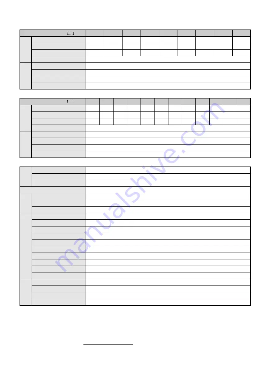
Model CIMR−R5A
23P7
3.7
13
10
25P5
5.5
19
15
27P5
7.5
26
20
2011
11
37
30
2015
15
51
40
2018
18.5
64
50
2022
22
77
60
2030
30
102
80
2037
37
126
100
Rated Capacity
Rated DC Current
Rated Current on Power Side
Regenerative Torque
Voltage Frequency
Allowable Voltage Fluctuation
Allowable Frequency Fluctuation
Imbalance Rate between Phases
200 to 220 VAC 50 Hz, 200 to 230 VAC 60 Hz
−15 to +10 %
±3 Hz/300 ms(Free phase rotation)
Within 2 %
*
150 % for 30 sec. 100 % for 1 min., 25 % ED, 80 % continuous
kW
A
A
200V Class
Rating
Input Power
Supply
Rating
Input Power
Supply
Model CIMR−R5A
43P7
3.7
6
5
45P5
5.5
9
7.5
47P5
7.5
13
10
4011
11
19
15
4015
15
26
20
4018
18.5
32
25
4022
22
37
30
4030
30
51
40
4037
37
64
50
4045
45
77
60
4055
55
96
75
4075
75
128
100
Rated Capacity
Rated DC Current
Rated Current on Power Side
Regenerative Torque
Voltage Frequency
Allowable Voltage Fluctuation
Allowable Frequency Fluctuation
Imbalance Rate between Phases
380 to 460 VAC 50/60 Hz
−15 to +10 %
±3 Hz/300 ms(Free phase rotation)
Within 2 %
*
150 % for 30 sec. 100 % for 1 min., 25 % ED, 80 % continuous
kW
A
A
400V Class
Control Method
Input Power Factor
Overload Capacity
Operation Input
1C Contact Output
Photocoupler Output
Analog Output
Instantaneous Overcurrent
Blown Fuse
Overload
Undervoltage (DC Voltage)
Undervoltage (Power Side Voltage)
Overvoltage (DC Voltage)
Fin Overheat
Power Supply Open Phase
Power Frequency Error
Power Charge Indication
Location
Ambient Temperature
Humidity
Vibration
120°current conduction
0.9 or more (Rated current)
30 sec. at approx. 150 % of rated current.
External terminals 4 points (MANUAL RUN, AUTO RUN, EXFLT, RESET)
Fault (FAULT)
Photocoupler output 2 points (CONV READY, RUN)
Analog output: 1 point can be released (Factory setting: current monitor)
Stops at approx, 200 % of the current on power side
Motor stops by blown fuse.
Stops after 30 sec. at 150 % of rated current
200 V class: stops at approx. 190 VDC or less 400 V class: stops at approx. 380 VDC or less.
200 V class: stops at approx. 150 VAC or less 400 V class: stops at approx. 300 VAC or less.
200 V class: stops at approx. 406 VDC or more 400 V class: stops at approx. 812 VDC or more.
Protected by thermister
Stops at power supply open phase detection.
Stops by fluctuation more than ± 3 Hz of rated input frequency.
Indicated until main output voltage is approx. 50 V or less.
Indoor (Protected from corrosive gases and dust)
-10 to +40 ℃ (Closed wall-mounted) -10 to +45 ℃ (Open chassis type)
90 % RH or less (non-condensing)
Up to 9.8 m/s
2
(1G) less than 20 Hz, up to 1.96 m/s
2
(0.2G) at 20 to 50 Hz
Common to 200V/400V Class
Control
Characteristics
Status
Output
Protective Function
Environmental
Conditions
STANDARD SPECIFICATIONS


