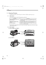


1.3 Examples of Servo System Configurations
1-9
1
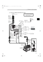
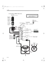
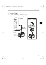
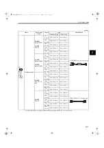
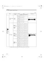
(3) Connecting to SGMSS Servomotors
SynqNet communication cables
SynqNet controller
and/or nodes
External LED display
or external switches
I/O signal cable
SGDS-
72A
(Refer to
5.4
.)
Brake power supply
Servomotor
main circuit cable
Encoder cable
Battery case
Magnetic contactor
Regenerative
resistor
Noise filter
Molded-case
circuit breaker
(MCCB)
Magnetic
contactor
SGMSS
Servomotor
Power supply
Single-phase 200 VAC
R S T
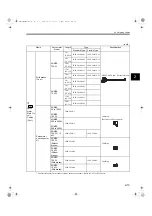
Protects the power supply
line by shutting the
circuit OFF when
overcurrent is
detected.
(Refer to
4.4.8 Molded-
case Circuit Braker (MCCB)
.)
Used to eliminate
external noise from the
power line.
(Refer to
4.4.9.
)
Connect an external
regenerative resistor
to terminals B1 and B2
if the regenerative capacity
is insufficient.
(Refer to
4.4.6 External
Regenerative Resistor
.)
Used for a servomotor with a brake.
(Refer to
4.4.5 Brake Power Supply
Unit
.)
Turns the servo
ON and OFF.
Install a surge
protector.
(Refer to
4.4.10 Magnetic
Contactor
.)
Turns the brake power supply
ON and OFF.
Install a surge protector.
(Refer to
4.4.10 Magnetic Contactor
.)
(when an absolute encoder
is used.)
(Refer to
4.4.7 Absolute
Encoder Battery.)
3. For connecting the AC/DC reactor, refer to
5.4.5 AC/DC Reactor for Harmonic Suppression
.
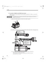
Notes: 1. For single-phase 200V 800W SERVOPACKS,
the terminal L3 is not used. Do not connect.
2. Remove the lead wire between the terminals
B2 and B3 on the SERVOPACK before
connecting an external regenerative resistor
to the SERVOPACK.
SIEPS80000025.book 9 ページ 2004年10月25日 月曜日 午前11時57分


