


5.5 Connecting Regenerative Resistors
5-21
5
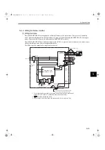
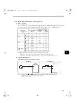
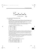
(3) Precautions on Selecting External Regenerative Resistors
A built-in regenerative resistor is provided for 750 W to 3.0 kW SGDS SERVOPACKs as standard.
When installing an external regenerative resistor, make sure that the resistance is the same as that of the
SERVOPACK’s built-in resistor.
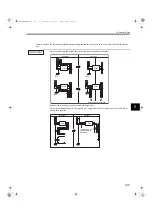
If combining multiple small-capacity regenerative resistors to increase the regenerative resistor capacity (W),
select resistors so that the resistance value including error is at least as high as the minimum allowable resistance
shown in the above table.
Connecting a regenerative resistor with the resistance smaller than the minimum allowable resistance may
increase the current flow in the regeneration circuit, resulting in damage to the circuit.
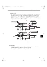
(4) Parameter Setting
1. When resistors for power are used at the rated load ratio, the resistor temperature increases to between
200
°
C and 300
°
C (392
°
F and 572
°
F). The resistors must be used at or below the rated values. Check
with the manufacturer for the resistor’s load characteristics. Use resistors at no more than 20% of the
rated load ratio with natural convection cooling, and no more than 50% of the rated load ratio with
forced air cooling.
2. For safety’s sake, use the resistors with thermoswitches.
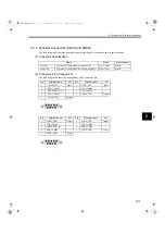
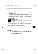
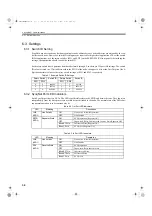
Pn600
Regenerative Resistor Capacity
Setting Range
Unit
Factory Setting
Setting Validation
0 to SERVOPACK
capacity
10 W
0 W
Immediately
Be sure to set this parameter when installing an external regenerative resistor.
When set to the factory setting of “0,” the SERVOPACK’s built-in resistor has been used.
Set the regenerative resistor capacity tolerance value. When the set value is improper, alarm A.320 is not detected normally.
Also, do not set other than 0 without connecting the regenerative resistor because alarm A.300 or A.330 may be detected.
The set value differs depending on the cooling method of external regenerative resistor:
• For natural air cooling method: Set the value maximum 20% of the actually installed regenerative resistor capacity (W).
• For forced air cooling method: Set the value maximum 50 % of the actually installed regenerative resistor capacity (W).
Example: Set 20 W (100 W
×
20%
) For the 100 W external regenerative resistor with natural cooling method: Pn600 = 2
(units: 10 W)
IMPORTANT
SIEPS80000025.book 21 ページ 2004年10月25日 月曜日 午前11時57分


