


9 Inspection, Maintenance, and Troubleshooting
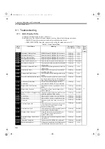
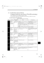
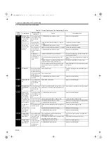
9.1.3 Troubleshooting of Alarm and Warning
9-8
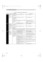
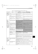
A.320
Regenerative
Overload
(Detected when
the power to the
main circuit was
turned ON)
Occurred when the
control power sup-
ply was turned
ON.
A SERVOPACK board fault occurred.
Replace the SERVOPACK.
Occurred when the
main circuit power
supply was turned
ON
The power supply voltage is 270 V or more.
Correct the input voltage.
Occurred during
normal operation.
(large increase of
regenerative resis-
tor temperature)
The regenerative energy is excessive.
Select a proper regenerative resistance capac-
ity, or reconsider the load and operation condi-
tions.
The regenerating state continued.
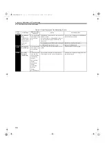
Occurred during
normal operation.
(small increase of
regenerative resis-
tor temperature)
The set value of parameter Pn600 is smaller than
the external regenerative resistor capacity.
Correct the set value of parameter Pn600.
A SERVOPACK fault occurred.
Repalce the SERVOPACK.
Occurred at servo-
motor decelera-
tion.
The regenerative energy is excessive.
Select a proper regenerative resistance capac-
ity, or reconsider the load and operation condi-
tions.
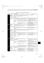
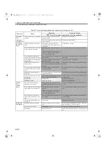
A.330
Main Circuit
Wiring Error
(Detected when
the power to the
main circuit was
turned ON)
Occurred when the
control power sup-
ply was turned
ON.
A SERVOPACK board fault occurred.
Replace the SERVOPACK.
Occurred when the
main circuit power
supply was turned
ON.
In DC power input mode, AC power is supplied
through L1 and L2 or L1, L2, and L3.
For AC power input, set Pn001.2=0.
For DC power input, set Pn001.2=1.
In AC power input mode, DC power is supplied
through B1/ and terminals.
Pn600 is set to 0 if regenerative resistance is dis-
connected.
Set Pn600 to 0.
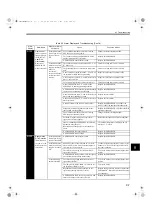
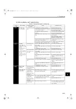
A.400
Overvoltage
(Detected when
the
SERVOPACK
main circuit DC
voltage is
approx. 410 V or
more)
(Detected when
the power to the
main circuit was
turned ON)
Occurred when the
control power sup-
ply was turned
ON.
A SERVOPACK board fault occurred.
Replace the SERVOPACK.
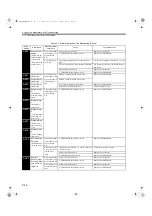
Occurred when the
main circuit power
supply was turned
ON.
The AC power voltage is 290 V or more.
AC power voltage must be within the specified
range.
A SERVOPACK fault occurred.
Replace the SERVOPACK.
Occurred during
normal operation.
Check the AC power voltage (no excessive volt-
age change?)
AC power voltage must be within the specified
range.
High motor speed and excessive load moment of
inertia (insufficient regenerative capacity)
Reconsider the load and operation conditions
(check the load moment of inertia and minus
load specifications.)
A SERVOPACK fault occurred.
Replace the SERVOPACK.
Occurred at servo-
motor decelera-
tion.
High motor speed and excessive load moment of
inertia
Reconsider the load and operation conditions.
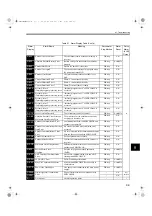
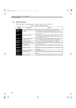
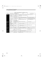
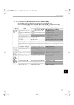
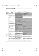
Table 9.3 Alarm Display and Troubleshooting (Cont’d)
Alarm
Display
Alarm Name
Situation at Alarm
Occurrence
Cause
Corrective Actions
SIEPS80000025.book 8 ページ 2004年10月25日 月曜日 午前11時57分


