
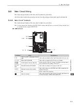
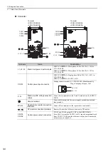


3.1 Main Circuit Wiring
3-9
3
Wi
ring and
C
onne
ctio
n
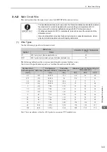
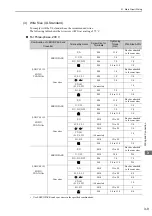
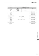
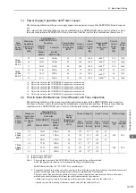
(3) Wire Size (UL Standard)
To comply with the UL standard, use the recommended wires.
The following table shows the wire sizes (AWG) at a rating of 75
°
C.
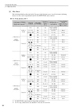
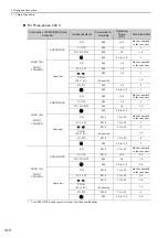
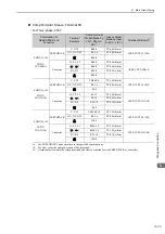
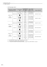
For Three-phase, 200 V
∗
Use SERVOPACKs and converters in the specified combinations.
Combination of SERVOPACK and
Converter
*
Terminal Symbols
Screw Size for
Terminals
Tightening
Torque
(N m)
Wire Size AWG
SGDV-121H
SGDV-
COA2BAA
SERVOPACK
P, N
M8
15.0
Bus bar attached
to the converter
U, V, W
M8
3.0
1/0
DU, DV, DW
M6
3.0
10
M8
9.0 to 11.0
1/0
Converter
P, N
M8
3.0
Bus bar attached
to the converter
L1, L2, L3
M8
3.0
1/0
1, 2
M8
3.0 1/0
CN101
(L1C, L2C)
–
(Connector)
–
14
B1, B2
M8
3.0
6
M8
9.0 to 11.0
1/0
SGDV-161H
SGDV-
COA3GAA
SERVOPACK
P, N
M8
15.0
Bus bar attached
to the converter
U, V, W
M8
3.0
3/0
DU, DV, DW
M6
3.0
10
M8
9.0 to 11.0
3/0
Converter
P, N
M10
12 to 20
Bus bar attached
to the converter
L1, L2, L3
M10
12 to 20
3/0
1, 2
M10
12 to 20
3/0
CN101
(L1C, L2C)
–
(Connector)
–
14
B1, B2
M10
12 to 20
4
M8
9.0 to 11.0
3/0
SGDV-201H
SGDV-
COA3GAA
SERVOPACK
P, N
M10
12 to 20
Bus bar attached
to the converter
U, V, W
M10
30.0
250
DU, DV, DW
M6
3.0
10
M8
9.0 to 11.0
250
Converter
P, N
M10
12 to 20
Bus bar attached
to the converter
L1, L2, L3
M10
12 to 20
4/0
1, 2
M10
12 to 20
4/0
CN101
(L1C, L2C)
–
(Connector)
–
14
B1, B2
M10
12 to 20
4
M8
9.0 to 11.0
4/0