


9 Troubleshooting
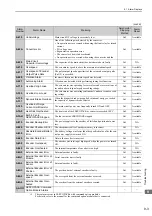
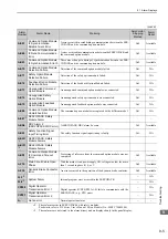
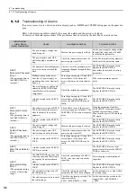
9.1.2 Troubleshooting of Alarms
9-10
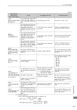
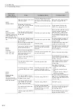
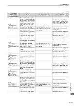
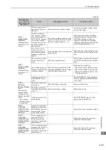
A.400:
Overvoltage
(Detected in the SER-
VOPACK main circuit
power supply section.)
The AC power supply voltage
exeeded:
• 290 VAC for 200-VAC SER-
VOPACKs.
• 580 VAC for 400-VAC SER-
VOPACKs.
Measure the power supply voltage.
Set AC power supply voltage within
the specified range.
The power supply is unstable, or
was influenced by a lightning
surge.
Measure the power supply voltage.
Improve the power supply condi-
tions by installing a surge absorber,
etc. Then, turn the power supply
OFF and ON again. If the alarm still
occurs, the SERVOPACK or con-
verter may be faulty. Replace the
SERVOPACK or converter.
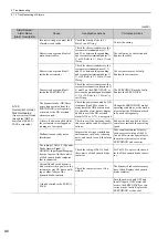
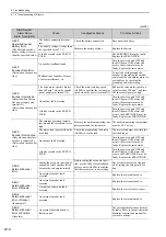
Voltage for AC power supply was
too high during acceleration or
deceleration.
Check the power supply voltage and
the speed and torque during opera-
tion.
Set AC power supply voltage within
the specified range.
The regenerative resistance is too
high for the actual operating con-
ditions.
Check the operating conditions and
the regenerative resistance.
Select a regenerative resistance
value appropriate for the operating
conditions and load.
The moment of inertia ratio
exceeded the allowable value.
Confirm that the moment of inertia
ratio is within the allowable range.
Increase the deceleration time, or
reduce the load.
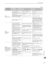
The fuse in the converter’s regen-
eration circuit is blown out.
Check for a Regeneration Error
alarm (A.300) and check the
CHARGE indicator on the con-
verter to see if it remains lit for
more than a few seconds immedi-
ately after the main circuit power
supply is turned OFF.
The converter may be faulty.
Replace the converter.
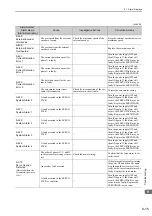
The connection of the I/O signals
(CN901) between the SERVO-
PACK and converter is faulty.
Check the connection of CN901.
Correctly connect CN901.
A fault occurred in the SERVO-
PACK or converter.
−
Turn the control power OFF and
then ON again while the main cir-
cuit power supply is OFF. If the
alarm still occurs, the SERVO-
PACK or converter may be faulty.
Replace the SERVOPACK or con-
verter.
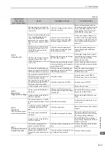
A.410:
Undervoltage
(Detected in the SER-
VOPACK main circuit
power supply section.)
The AC power supply voltage
dropped to:
• 120 V or less for 200-VAC
SERVOPACKs.
• 240 V or less for 400-VAC
SERVOPACKs.
Measure the power supply voltage.
Set the power supply voltage within
the specified range.
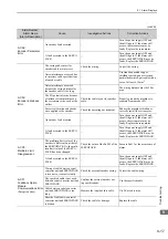
The power supply voltage
dropped during operation.
Measure the power supply voltage.
Increase the power supply capacity.
Occurrence of instantaneous
power interruption.
Measure the power supply voltage.
When the instantaneous power cut
hold time (Pn509) is set, decrease
the setting.
The converter fuse is blown out.
−
Replace the converter, connect a
reactor, and run the SERVOPACK
and converter.
The 1 and 2 terminals of the
converter are open.
Check the 1 and 2 terminals on
the converter.
Correctly connect the 1 and 2
terminals on the converter.
A fault occurred in the SERVO-
PACK or converter.
−
The SERVOPACK or converter
may be faulty. Replace the SERVO-
PACK or converter.
(cont’d)
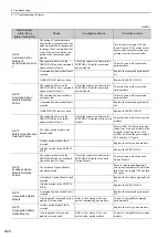
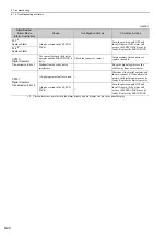
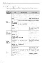
Alarm Number:
Alarm Name
(Alarm Description)
Cause
Investigative Actions
Corrective Actions