


11-1
171469-1CD
HW0485750
MH5
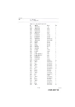
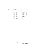
11 Parts List
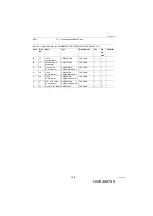
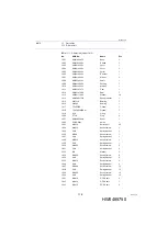
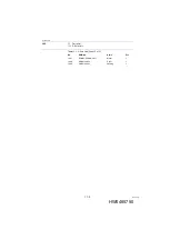
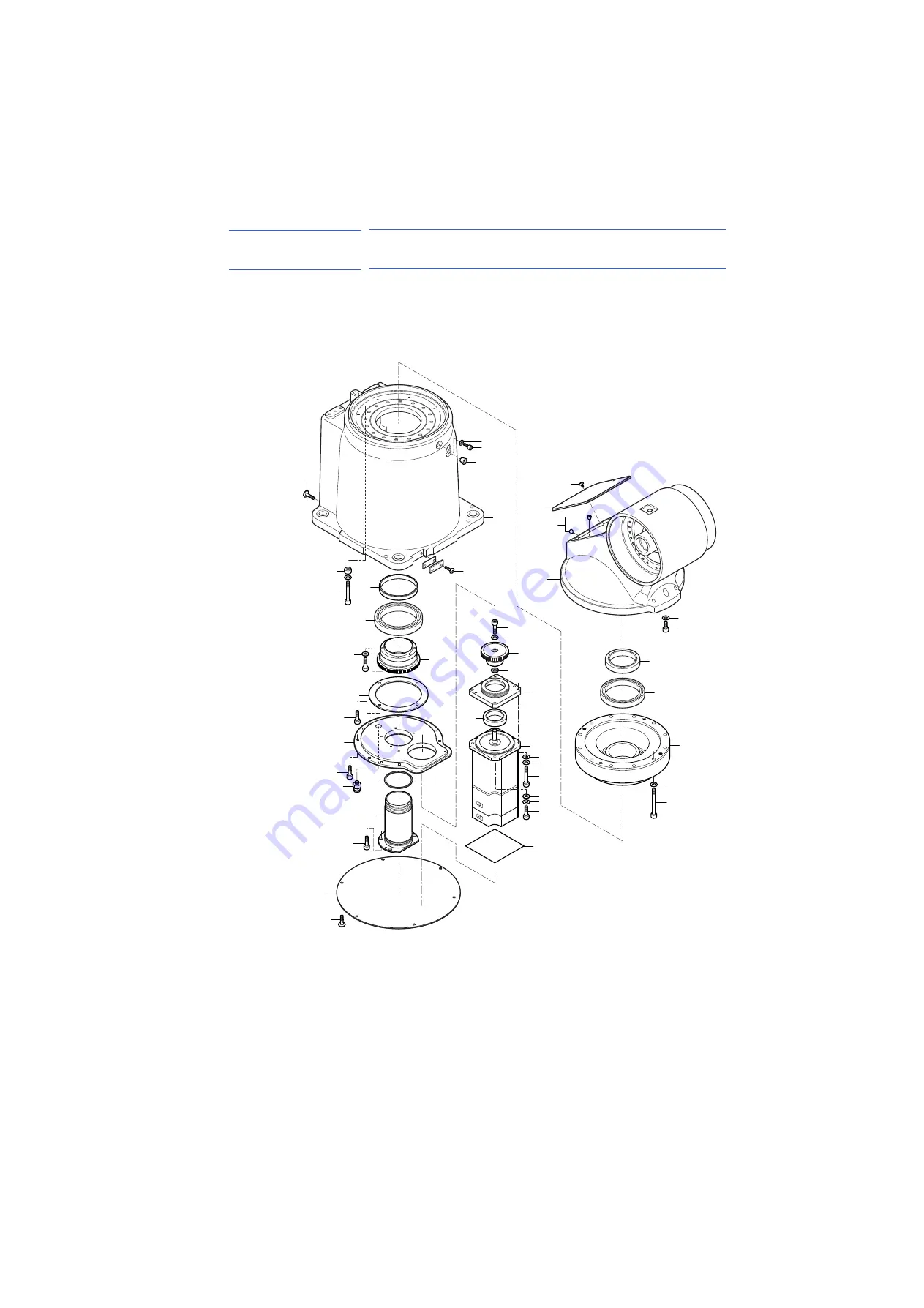
11.1 S-Axis Unit
11 Parts List
11.1
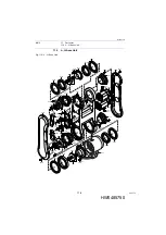
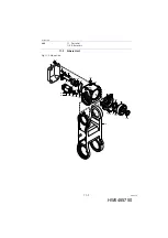
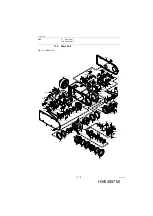
S-Axis Unit
Fig. 11-1: S-Axis Unit
1001
1049
1023
1048
1020
1027
1038
1037
1014
1026
1047
1032
1031
1030
1021
1032
1036
1035
1002
1017
1016
1004
1023
1010
1018
1009
1011
1029
1028
1007
1008
1019
1045
1022
1043
1041
1006
1034
1033
1003
1020
1023
1005
1013
1040
1039
1023
1015
1012
1025
1024
63 of 74