background image

32

3.4  WIRING PRECAUTIONS

(1)

Wiring Leading-in Method

Lead in the wire through the knockout hole on the unit bottom. Since the 
knockout hole is provided with a rubber bush, cut the rubber bush central 
crosswise with a blade and lead the wire through. 

(2)

Separation from Signal Lines

Since strong noise component is superimposed on the braking resistor unit 
and braking unit wiring, separate the units from signal lines which are weak 
against noise.

(3)

Wiring Distance

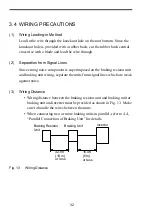
•  Wiring distance between the braking resistor unit and braking unit or 

braking unit and inverter must be provided as shown in Fig. 13.  Make 
sure to bundle the wires between the units.

•  When connecting two or more braking units in parallel, refer to 4.4, 

“Parallel Connection of Braking Unit” for details.

Fig. 13

Wiring Distance

Braking Resistor
Unit

Braking Unit

Inverter

32.8ft
(10 m)
or less

16.4ft
(5 m)
or less

Содержание CDBR Series

Страница 1: ...aking unit Braking resistor unit YASKAWA AC Drive Option Installation Manual To properly use the product read this manual thoroughly and retain for easy reference inspection and maintenance Ensure the...

Страница 2: ...ough under standing of this manual is recom mended This instruction manual will be of great help for daily maintenance inspection and troubleshoot ing Inverters to which the braking resistor unit and...

Страница 3: ...presented examples some are subject to differ from delivered products S This manual may be modified when necessary because of improvement of the product modification or changes in specifications Such...

Страница 4: ...tion which if not avoided could result in death or serious injury to personnel Indicates a potentially hazardous situation which if not avoided may result in minor or moderate injury to personnel and...

Страница 5: ......

Страница 6: ...gered Failure to observe this warning can result in a fire 27 When wiring the emergency stop circuit check the wiring thoroughly before operation Failure to observe this warning can result in personal...

Страница 7: ...istors braking resistor units and braking units as shown in the I O wiring examples Use properly rated wire in accordance with table 2 on page 31 Otherwise a fire can occur 27 S Tighten terminal screw...

Страница 8: ...ock 41 CAUTION Ref page S Never touch the heatsink or discharging resistor since the temperature is very high Failure to observe this caution can result in harmful burns to the body 41 S Do not check...

Страница 9: ......

Страница 10: ...c electricity 46 S Donotconnectordisconnectwiresorconnectorswhilepower is applied to the circuit Failure to observe this caution can result in personal injury 46 OTHERS WARNING S Never modify the prod...

Страница 11: ...ing unit as shown below Follow these instructions when handling the braking unit and the braking resistor unit Exampleof BrakingUnit ModelCDBR 4045B Warning Indication 4 0 70 6 UGV VJG EQPPGEVQTU DGHQ...

Страница 12: ...13 Warning Indication...

Страница 13: ...3 4 OPERATION 41 4 1 ADJUSTMENT 41 4 2 POWER SUPPLY VOLTAGE SELECTION CONNECTOR SETTING 41 4 3 MASTER SLAVE SELECTION CONNECTOR SETTING 44 4 4 PARALLEL CONNECTION OF BRAKING UNIT 44 4 5 OPERATION 45 5...

Страница 14: ...ined no damage while in transit Fastening bolts and screws are not loose 1 1 NAMEPLATE 1 NAMEPLATE INFORMATION BRAKING UNIT 2 NAMEPLATE INFORMATION BRAKING RESISTER UNIT Do not install and attempt to...

Страница 15: ...90 RH or less no condensation Free from vibration 2 2 INSTALLATION For full use of the braking resistor unit or braking unit functions install the units at pollution level 2 or less UL standard and in...

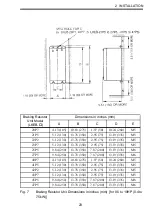
Страница 16: ...talled vertically Fig 1 Braking Unit Dimensions in inches mm CDBR 2015B 2015C 2022B 2022C 4030B 4045B 4 M4 MTG HOLE 1 5 38 1 5 38 1 18 30 OR MORE 3 LEAD WIRE OUTLET 0 87 20 DIA RUBBER BUSH 5 04 128 5...

Страница 17: ...18 30 OR MORE 58 5 2 19 55 5 11 02 280 10 23 260 9 25 235 0 39 10 1 14 29 3 94 100 MAIN CIRCUIT TERMINAL M4 3 LEAD WIRE OUTLET 1 10 28 DIA RUBBER BUSH 4 M6 MTG HOLE 2 30 1 18 30 OR MORE 3 94 100 OR MO...

Страница 18: ...11 6 14 156 7 87 200 3 86 98 3 94 100 2 95 75 12 48 317 13 78 350 14 57 370 1 44 36 5 0 47 12 5 51 140 MAIN CIRCUIT TERMINAL M5 2 LEAD WIRE OUTLET 1 38 35 DIA RUBBER BUSH 4 M6 MTG HOLE 3 94 100 OR MOR...

Страница 19: ...0 OR MORE WIRE OUTLET 1 10 28 DIA RUBBER BUSH 3 94 100 OR MORE 12 48 317 13 78 350 14 57 370 1 44 36 5 0 47 12 3 94 100 2 87 73 5 51 140 5 51 140 59 7 09 180 2 32 1 97 50 1 18 30 OR MORE 1 18 30 OR MO...

Страница 20: ...38 5 2 95 75 8 66 220 68 5 7 09 180 2 70 1 97 50 1 18 30 OR MORE 1 18 30 OR MORE 2 LEAD WIRE OUTLET 1 38 35 DIA RUBBER BUSH WIRE OUTLET 1 10 28 DIA RUBBER BUSH 3 94 100 OR MORE 4 37 111 6 14 156 7 87...

Страница 21: ...2 76 70 6 16 156 5 8 27 210 4 67 118 5 1 97 50 1 18 30 OR MORE 9 84 250 1 18 30 OR MORE 2 LEAD WIRE OUTLET 1 38 35 DIA RUBBER BUSH WIRE OUTLET 1 10 28 DIA RUBBER BUSH 3 94 100 OR MORE 4 37 111 6 14 1...

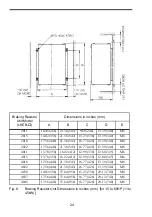
Страница 22: ...M5 22P2 5 12 130 13 78 350 2 95 75 13 19 335 M5 23P7 5 12 130 13 78 350 2 95 75 13 19 335 M5 25P5 9 84 250 13 78 350 7 87 200 13 19 335 M6 27P5 9 84 250 13 78 350 7 87 200 13 19 335 M6 40P7 4 13 105...

Страница 23: ...40 M8 2018 17 56 446 21 38 543 16 77 426 13 39 340 M8 2022 17 56 446 21 38 543 16 77 426 13 39 340 M8 4011 13 78 350 16 22 412 12 99 330 12 80 325 M6 4015 13 78 350 16 22 412 12 99 330 12 80 325 M6 40...

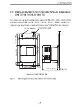
Страница 24: ...ew units CDBR 2015B 2015C 2022B 2022C 4030B 4045B an exclusive use attachment is required Contact your YASKAWA representative Fig 9 Mounting Dimensions of Attachment in inches mm 0 39 10 0 28 7 3 94 1...

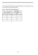
Страница 25: ...inal symbols are different between conventional models and new models Refer to the following table Table 1 Main Circuit Terminal Symbols Conventional Models Example CDBR 2015 New Models Example CDBR 2...

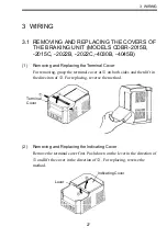
Страница 26: ...over For removing grasp the terminal cover at c on borh sides and then lift in the direciton of d For replacing reverse the method 2 Removing and Replacing the lndicating Cover Remove the terminal cov...

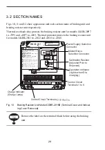
Страница 27: ...4018 to 4045 Fig 10 Braking Resistor Unit Model CDBR 2015B Terminal Cover and Indicat ing Cover Removed Remove the label on the terminal block before using the braking unit 1 4 8 55 14 M9 4 0 70 6 56...

Страница 28: ...0 mm further inside the unit when compared to the same models for SPEC A 2 External terminals for SPEC B models LKEB 21P5 to 27P5 and LKEB 41P5 to 47P5 are located up to 15 mm higher on the unit when...

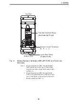
Страница 29: ...30 Resistor Thermal Overload Protector Control Circuit Terminals B P 1 2 Lead Wire Outlet Rubber Bush Fig 12 Braking Resistor Unit Model LKEB 2022 Front Cover Removed...

Страница 30: ...re Size AWG mm2 Wire Type Terminal Screw Max Torque lb in N m Braking Unit Models CDBR 2015B 2015C 2022B 2022C 4030B 4045B 5037B Main 0 0 12 10 3 5 5 5 600V High Voltage 3 vinyl sheathed wire or equiv...

Страница 31: ...braking resistor unit and braking unit wiring separate the units from signal lines which are weak against noise 3 Wiring Distance Wiring distance between the braking resistor unit and braking unit or...

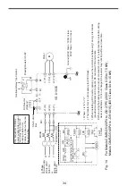
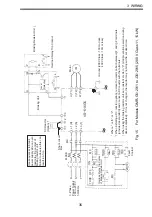
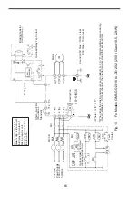
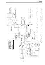
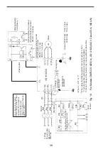
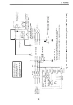
Страница 32: ...interconnecting diagrams of the braking unit or braking resistor unit and VS 616G5 Refer to Par 3 3 Wiring Precautions for proper wiring in actual wiring design and work Be sure to connect braking re...

Страница 33: ...r supply side on over load relay trip contact of braking resistor unit Failure to observe this can result in a fire The transformer is not necessary for 200V class Where is E or V When installing a DC...

Страница 34: ...ss 100 or less 400V Class 10 or less Where is E or V When installing a DC reactor option remove the common bar between 1 and 2 terminals provided as standard and connect a DC reactor with the terminal...

Страница 35: ...Fan 2 r 1 U T1 V T2 W T3 3 Phase Power Supply 200 to 230 V 50 60 Hz Use sequencer to break power supply side on over load relay trip contact of braking resistor unit Failure to observe this can result...

Страница 36: ...king Resistor Unit Fault Contact Voltage Selection 460 440 415 400 380V 400 200V U T1 V T2 W T3 Ground 200V Class 100 or less 400V Class 10 or less Where is E or V When using the braking resistor unit...

Страница 37: ...ooling Fin Overheat Contact Thermoswitch Contact 250VAC 1A or less 30VDC 1A or less U T1 V T2 W T3 L1 R L2 S L3 T 0 0 460 440 415 400 380V Use sequencer to break power supply side on over load relay t...

Страница 38: ...Overload Relay Trip Contact of Braking Resistor Unit Fault Contact 2 3 Phase Power Supply 200 to 230 V 50 60 Hz 0 0 Ground 200V Class 100 or less 400V Class 10 or less Where is E or V When using the b...

Страница 39: ...400 3 Phase Power Supply 380 to 460 V 50 60 Hz Overload Relay Trip Contact of Braking Resistor Unit Fault Contact 0 0 460 440 415 400 380V Ground 200V Class 100 or less 400V Class 10 or less Where is...

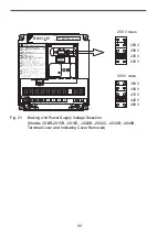
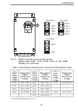
Страница 40: ...SELECTION CON NECTOR SETTING It may be necessary to select power supply voltage selection connector for braking unit according to main circuit power supply type Table 3 shows the relationship between...

Страница 41: ...on Models CDBR 2015B 2015C 2022B 2022C 4030B 4045B Terminal Cover and Indicating Cover Removed 1 4 8 55 14 M9 4 0 70 6 7UG q EQRRGT YKTGU QPN 4GHGT VQ OCPWCN HQT EQPPGEVKQPU 200 V 208 V 220 V 230 V 40...

Страница 42: ...s Table 3 Power Supply Voltage Selection Connector and Braking Start Voltage 200 V Class Power Supply Voltage Braking Start Voltage PN Bus bar Voltage 400 V Class Power Supply Voltage Braking Start Vo...

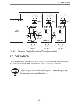
Страница 43: ...ct the connectors as follows See Fig 23 Braking units have a MASTER SLAVE selection connector See Fig 10 Select MASTER side only for braking unit 1 and select SLAVE side for braking units 2 and 3 Prop...

Страница 44: ...Relay Trip Contact Braking Resistor Unit Braking Resistor Unit Braking Resistor Unit Braking Unit 2 15 5 1 2 6 SLAVE MASTER Level Detector Cooling Fin Overheat Contact Thermoswitch Contact Master Uni...

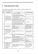
Страница 45: ...Insufficient braking resistor unit capacity Examine the braking conditions again Improper wiring Check and repair Braking unit fault Replace the unit 3 Braking resistor unit overload relay or thermal...

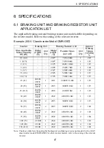
Страница 46: ...Braking Torque 10 ED Max Applicable Motor Capacity HP kW Model CDBR Unit Q ty Model LKEB Resistor Spec per unit Unit Q ty 0 5 0 4 20P7 70W 200 1 220 1 0 75 20P7 70W 200 1 125 2 1 5 21P5 260W 100 1 12...

Страница 47: ...15 4015 1560W 40 1 125 25 18 5 4030B 1 4018 4800W 32 1 125 30 22 4030B 1 4022 4800W 27 2 1 125 40 30 4030B 1 4030 6000W 20 1 125 50 37 4045B 1 4037 9600W 16 1 125 60 45 4045B 1 4045 9600W 13 6 1 125 7...

Страница 48: ...Inverter Braking Unit Braking Resistor Unit Approx Braking Torque 10 ED Max Applicable Motor Capacity HP kW Model CDBR Unit Q ty Resistor Spec 5 3 7 560W 150 180 7 5 5 5 560W 150 125 10 7 5 750W 100 1...

Страница 49: ...xam ples of Fig 14 VS 616HII H3 VS 616GII G3 VS 676 Model CDBR 15H etc Model LKEB 2015 etc Applicable Use sequencer to break power supply side on thermal protector of the braking resistor unit side VS...

Страница 50: ...330 345 365 380V 3V 630 660 690 730 760V 6V 825V 950V 8V Max Hysteresis Error Approx 8V Approx 16V Approx 20V Power Supply VDC 243 1 35 200 0 9 to 400V peak 460 1 35 380 0 9 to 800V peak 607 1 35 500...

Страница 51: ...89 1 1 23P7B 390W 40 150 1 9 25P5B 520W 30 220 2 7 27P5B 780W 20 300 3 9 2011 2400W 13 6 440 5 7 2015 3000W 10 600 7 7 2018 4800W 8 740 9 6 2022 4800W 6 8 880 11 4 40P7B 380 to 460V 70W 750 30 0 20 41...

Страница 52: ...R 2015C 72600 R2150C 30 22 CDBR 2022B 72600 R2220B CDBR 2022C 72600 R2220C 60 45 CDBR 2045B 72600 R2450B 150 110 CDBR 2110B 72600 R21100B 380 to 460 V 40 30 CDBR 4030B 72600 R4300B 60 45 CDBR 4045B 72...

Страница 53: ...00 K2150 25 18 5 4800W 8 LKEB 2018 72600 K2180 30 22 4800W 6 8 LKEB 2022 72600 K2220 380 to 460V 1 0 75 70W 750 LKEB 40P7 72600 K4P70B 2 1 5 260W 400 LKEB 41P5 72600 K4010B 3 2 2 260W 250 LKEB 42P2 72...

Страница 54: ...angPu District Shanghai 200003 China Phone 86 21 5385 2200 Fax 86 21 5385 3299 http www yaskawa com cn YASKAWA ELECTRIC CHINA CO LTD BEIJING OFFICE Room 1011 Tower W3 Oriental Plaza No 1 East Chang An...

Отзывы: