Yardworks 60-3982-0 Скачать руководство пользователя страница 4

4

GENERAL SAFETY RULES

Electrical Information


WARNING:


To avoid electrical hazards, fire hazards, or damage to the tool, use proper circuit protection. 

                The Snow Thrower is wired at  the factory for 120 V operation. Connect to a 120 V, 15 A circuit and use a 

                15 A time delayed fuse or circuit breaker. To avoid shock or fire when the power cord is worn, cut, or 

damaged in any way, replace it immediately.

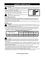
This Snow Thrower has a 3-prong plug that is intended for use on a circuit 

that has a receptacle like the one illustrated in Fig. A.

Do not modify the power cord plug. If it does not match the electrical outlet, 

have the proper outlet installed by a qualified electrician.


WARNING: 

To avoid injury, when servicing the Snow Thrower,

               use only identical replacement parts.

IN THE EVENT OF A MALFUNCTION OR BREAKDOWN, grounding provides the path of least resistance for 

electrical current and reduces the risk of electric shock. This tool is equipped with an electric cord that has a 

POLARIZED plug. The plug MUST be plugged into a matching outlet that is properly installed and grounded in 

accordance with ALL local codes and ordinances.

DO NOT MODIFY THE PLUG PROVIDED. If it will not fit the outlet, have the proper outlet installed by a qualified 

electrician.

Extension Cord


                WARNING:

 In order to reduce the risk of electric shock when operating this Snow Thrower, use only a 

                CSA-listed extension cord that is approved for outdoor use, such as Type SJTW, 16AWG, and that has 

                a lower temperature rating of -40° F (-40° C).

• Ground Fault Circuit Interrupter (GFCI) protection should be provided on the circuit(s) or outlet(s) that will be 

used for this Snow Thrower. For an extra measure of safety, use a receptacle that has built-in GFCI protection.

• The nameplate on the Snow Thrower indicates the voltage used. Do not connect the Snow Thrower to an AC 

circuit that provides a different voltage from the voltage that is indicated on the nameplate.


                WARNING:

 In order to prevent electric shock, use an extension cord that is suitable for outdoor use.

• Inspect the extension cord and the power cord on a regular basis. Look for deterioration, cuts, or cracks in the 

insulation. Inspect the connections for damage. Repair or replace the extension cord or the power cord if any 

damage is found.

• Verify that the rotor and all moving parts have come to a complete stop, and disconnect the Snow Thrower from

the power supply in order to prevent accidental start-ups before cleaning or performing any inspections or repairs.

• Do not abuse the extension cord. Do not carry the Snow Thrower by the power cord or pull on the cord in order 

to disconnect it from the receptacle.

• Keep the extension cord away from heat, oil, and sharp edges in order to prevent damage.

• If the extension cord is damaged in any manner while it is plugged in, disconnect it from the outlet immediately.

• Avoid accidental start-ups. Do not carry the Snow Thrower with a finger on the switch while it is plugged in. 

Verify that the switch is in the "OFF" position before plugging in the Snow Thrower.

• Unplug the Snow Thrower and allow it to cool down before putting it into storage. Store the Snow Thrower indoors.

• Unplug the Snow Thrower when it is not in use and before performing any maintenance or repairs.

Amperage rating of the tool  

                              Total length of the extension cord  

       (120 V circuit only)   


    25’                   50’                 100’                150’  

                                                                 (7.6 m)              (15.2 m)           (30.4 m)           (45.7 m) 
More than  

Not more than    

        Minimum Gauge for the extension cord (AWG)  

        0    

        12  


    16    

   16    

  14  


 14  

Recommended size of extension cords

[Use the same format for the table as found in the file entitled "Recommended size of extension cords".]

Grounding Instructions

SAVE THESE SAFETY RULES

1

2

1) 3-prong plug

2) Receptacle with grounding conductor

Fig. A

Содержание 60-3982-0

Страница 1: ...Electric Snow Thrower 60 3982 0 Owner s Manual TOLL FREE HELPLINE 1 866 523 5218 IMPORTANT Read all safety rules and instructions carefully before using this product ...

Страница 2: ... 14 Troubleshooting 15 Warranty 16 Exploded View 17 Parts list 18 2 TABLE OF CONTENTS SPECIFICATIONS Motor 120 V 60 Hz 10 A Blade Speed Up to 2 600 RPM Clearing width 16 40 6 cm Clearing depth 6 15 2 cm Discharge distance Up to 25 7 6 m Impeller size 14 35 6 cm Wheels 6 15 2 cm Handle height 33 to 38 83 8 to 96 5 cm Weight 24 5 lbs 11 1 kg ...

Страница 3: ...ow Thrower 120 V 60 Hz 10 A 60 3982 0 Made in China Fabrique en Chine Serial N de serie CTxx xxxxxx 1 Read the instructions carefully Become familiar with the controls and the proper use of the Snow Thrower 2 Do not operate this Snow Thrower when tired ill or under the influence of alcohol drugs or medication 3 Do not allow children under the age of 14 to operate this Snow Thrower Children who are...

Страница 4: ...e Snow Thrower indicates the voltage used Do not connect the Snow Thrower to an AC circuit that provides a different voltage from the voltage that is indicated on the nameplate WARNING In order to prevent electric shock use an extension cord that is suitable for outdoor use Inspect the extension cord and the power cord on a regular basis Look for deterioration cuts or cracks in the insulation Insp...

Страница 5: ...ain in the starting position when turning the Snow Thrower on The operator and the Snow Thrower must be in a stable position during start up See the section entitled Starting Stopping Instruc tions Use the proper tool Only use this Snow Thrower for the purpose that it was designed for Do not overreach Always keep proper footing and balance Hold the Snow Thrower with both hands while it is in use K...

Страница 6: ...r in a dry area locked up or high enough to prevent unauthorized use or damage and out of the reach of children Do not douse or squirt the unit with water or any other liquid Keep handles dry clean and free of debris Clean the Snow Thrower after each use See the section entitled Cleaning and Storage If the labels on the Snow Thrower become defaced or start to lift off contact the Toll Free Helplin...

Страница 7: ...oles on the middle handle 2 Insert the bolts 5 and use the wing nuts 6 to tighten them 3 Align the holes 7 on the middle handle 2 and the lower handle 3 Insert the bolts 5 and tighten them using the wing nuts 6 provided Assembling the Discharge Directional Control Fig 1 1 Align the holes 11 on the upper tubing 8 with the holes on the lower tubing 9 Insert the hitch pin 10 Fig 1 1 2 10 11 8 8 5 4 6...

Страница 8: ... Diagram and Location of Parts Diagram and Location of Parts Fig 2 Upper Handle Middle Handle Lower Handle Wheels Cover Screws Scraper Belt Cover Discharge Directional Control Impeller Vanes Fig 2 Switch ...

Страница 9: ...st be in a stable position when starting the Snow Thrower Using the Switch Caution Do no attempt to override the operation of this safety switch This Snow Thrower is equipped with a special safety switch In order to operate the switch insert one finger into the opening and push the lever out so that it can be grasped along with the upper handle Pull the lever back in order to turn the Snow Thrower...

Страница 10: ...trol turns approximately 360 in either direction clockwise or counter clockwise Do not force it 2 Turn the discharge directional control clockwise 360 The vanes will turn approximately 45 to the left 3 Turn the discharge directional control counter clockwise 360 The vanes will turn approximately 45 to the right Tips for Best Snow Throwing Results For the most efficient snow throwing keep the vanes...

Страница 11: ...ken belt from the impeller pulley and the drive pulley inside the housing Discard the belt in the proper manner Fig 7 5 Loop the new belt around the drive pulley and the impeller pulley Fig 7 Pull the belt tensioner idler arm away from the drive pulley in order to install the belt around the drive pulley NOTE Verify that the washer is still in place on the impeller pulley shaft before reinstalling...

Страница 12: ...pellor and place the 2 washers on the right hand side 12 Place the impellor and shaft back into the front scoop 8 Remove the impellor shaft nut from the right hand side 9 Withdraw the impellor shaft from the left hand side 2 Remove the 10 screws from the side cover 3 Be sure not to lose the 2 springs 5 Remove the nut from the impellor shaft Remove the 3 screws holding the pulley support plate 6 Re...

Страница 13: ...sher and nut 19 Place the lower spring into position and slide the side cover up using slight pressure to hold the spring in place 20 Replace and tighten the remaining screws and the nut and washer 21 Re install the impellor shaft nut and washer on the right hand side and tighten 14 Be sure to route the belt correctly as shown 15 Replace the 2 spacer washers on the impellor shaft 13 14 15 16 17 18...

Страница 14: ...14 Fig 8 Fig 8 Fig 8 ...

Страница 15: ...e the belt see the section entitled Inspecting Replacing the Drive Belt Replace the scraper see the section entitled Replacing the Scraper The carriage bolts are not properly seated The Snow Thrower is unplugged The lock out button or trigger switch were not used properly The belt is damaged The scraper is worn Then handle is not in position The Snow Thrower does not start The motor is on but the ...

Страница 16: ...0 days from the date of retail purchase How to Obtain Service Warranty service is available with proof of purchase through your local authorized service dealer or distributor If you do not know the dealer or distributor in your area please call toll free 1 866 523 5218 The factory will not accept the return of a complete unit unless prior written permission has been extended by YARDWORKS CANADA Tr...

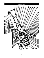
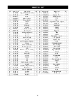
Страница 17: ...17 PARTS LIST ...

Страница 18: ...9 2 Right wheel assy 1 23 59 32262198 2 24 60 3420102 Strain relief 1 25 61 31100199 Pigtail cable 3320640 Loop Loop 1 26 62 1 27 63 Gasket Gasket 1 28 64 3290299 Gasket 3330211 3420199 Rubber washer 1 29 65 3330499 Screw 1 30 66 3330599 1 3290599 Nut 1 31 67 3410499 1 Handle 1 32 68 1 33 69 32901251 1 34 70 35 71 36 37 38 3411799 1 Left wheel assy 1 3411799C Wheel cover 2 3330398 Motor mounting b...

Отзывы: