YARDGARD SELECT
™
- FENCE FRAMEWORK INSTALLATION INSTRUCTIONS
PAGE 9
PAGE 8
YARDGARD SELECT
™
- FENCE FRAMEWORK INSTALLATION INSTRUCTIONS
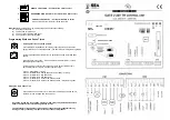
STAGE 2: FENCE PANEL INSTALLATION
2
STEP 2:
INSTALLING FENCE PANELS
IMPORTANT
Fence panels should be positioned on the
outside of the tension wire.
• Unfold one section of fence panel (8
´
). Attach panel to all three
panel-to-post brackets .
• Lift the fence panel section up into the rail. Insert a panel-to-
rail clip inside the rail connector cup. Make sure the top wire is
seated in the lip of the clip. Lock into place using supplied tool.
(Fig . 15)
TIP
If fence panel sections don’t align, tap panel-to-rail clips
gently until fence panel sections touch each other.
• Repeat this process for each 8´ section, positioning a clip in the
center of each 2´ panel (Fig. 16). Connect two panels together
by using three panel clips.
• Continue installing in 8´ sections until reaching the end of the
fence line.
• Hook the terminating panel section to the three panel-to-post
brackets on the terminating post and pull toward the previous
panel section. If the terminating panel is not an even 2´ you
will need to cut the panel at the closest vertical wire using wire
cutters. Flip panel so short panel connects to three post-to-
panel clips. Connect the two panel sections with three panel
clips. Secure the terminating fence panel to top rail by using
panel-to-rail clips . (Fig . 17)
• Fasten fence panel to each line post with panel-to-post clips
using self-tapping screws. (Fig. 18)
• Fasten top rail to each line posts using self tapping screws
inserted from the curved side.
• Attach tension wire to fence panels with panel-to-wire clip usin
g
adjustable pliers. Attach one clip every 2´.
1
2
3
Near center of each mesh panel
Inside of each rail connector cup
In both ends of each sleeve
1
2
1
1
3
3
1
2
Cut One Panel Short
Re-Connect with
Panel Clips or Hog Rings
Pull Down
to Lock
Panel-to-Rail Clip
Unlocked
Locked
End Panel Connection
2-ft x 4-ft
Fence Panel
Cut One Panel Short
Re-Connect with
Panel Clips or Hog Rings
Pull Down
to Lock
Panel-to-Rail Clip
Unlocked
Locked
End Panel Connection
2-ft x 4-ft
Fence Panel
AUTO CLOSE GATE
AUTO CLOSE GATE (1000-034-737)
QTY.
N
4’ Gate
1
O
Gate Latch
1
P
Self-Closing Gate Hinges
1
Q
PVC Post Protector
1
Self-Tapping Screws
5
OPTIONAL (AVAILABLE ON HOMEDEPOT.COM)
QTY.
R
Decorative fence
medallion*
4
Decorative fence
medallion*
1
TOOLS AND MATERIALS
•
Tape Measure
• Adjustable Wrench
• Cordless Drill
• 1/4
˝
Nut Driver
Fig . 15 Fence Panel Installation
Fig . 16 Locations of Panel-to-Rail Clips and
Panel Clips
Fig . 18 Fence Panel Installation
Fig . 17 Terminating Panel Installation
STAGE 3: PARTS LIST
Line Post
Cut
Panel Clips
Flip panel so short panel connects to
three post-to-panel clips.
Overlap the terminating panel to the
last full 8
´
section .
Red fence panel represents the terminating panel.
Self-Tapping Screw
Panel-to-Post Clip
STAGE 3: GATE INSTALLATION
3
Cut One Panel Short
Re-Connect with
Panel Clips or Hog Rings
Pull Down
to Lock
Panel-to-Rail Clip
Unlocked
Locked
End Panel Connection
2-ft x 4-ft
Fence Panel
Rail Connector
Wire
Panel-to-Post
Bracket
Panel-to-Rail Clip
Panel-to-Rail Clip Installation
Top Rail
(Cutaway View)
Locked
Pull Down
Insert
Locked
Pull Down
Insert
Locked
Pull Down
Insert
* Decorative fence medallion sold separately at homedepot.com