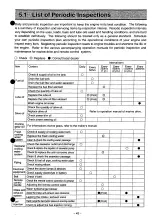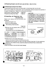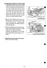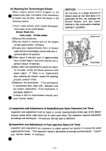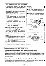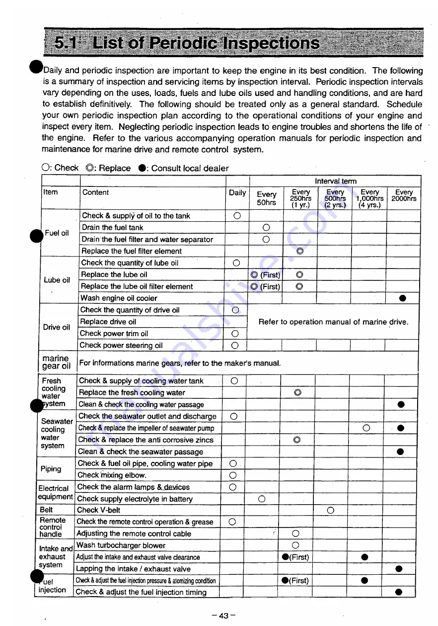
5.1 List of Periodic Inspections
'Daily and periodic inspection are important to keep the engine in its best condition. The following
is a summary of inspection and servicing items by inspection interval. Periodic inspection intervals
vary depending on the uses, loads, fuels and lube oils used and handling conditions, and are hard
to establish definitively. The following should be treated only as a general standard. Schedule
your own periodic inspection plan according to the operational conditions of your engine and
inspect every item. Neglecting periodic inspection leads to engine troubles and shortens the life of
the engine. Refer to the various accompanying operation manuals for periodic inspection and
maintenance for marine drive and remote control system.
O: Check ©: Replace • : Consult local dealer
Interval term
Item
Content
Daily
Every
50hrs
Every
250hrs
(1 yr.)
Every
500hrs
(2 yrs.)
Every
-LOOOhrs
(4 yrs.)
Every
2000hrs
m Fuel oil
Check & supply of oii to the tank
O
m Fuel oil
Drain the fuel tank
O
m Fuel oil
Drain the fuel filter and water separator
o
m Fuel oil
Replace the fuel filter element
©
Lube oil
Check the quantity of lube oil
o
Lube oil
Replace the lube oil
© (First)
©
Lube oil
Replace the lube oil filter element
© (First)
©
Lube oil
Wash engine oil cooler
•
Drive oil
Check the quantity of drive oil
o
Refer to operation manual of marine drive.
Drive oil
Replace drive oil
Refer to operation manual of marine drive.
Drive oil
Check power trim oil
o
Refer to operation manual of marine drive.
Drive oil
Check power steering oil
o
marine
gear oil For informations marine gears, refer to the maker's manual.
Fresh
cooling
water
Check & supply of cooling water tank
o
Fresh
cooling
water
Replace the fresh cooling water
©
•system
Clean & check the cooling water passage
•
Seawater
cooling
water
system
Check the seawater outlet and discharge
o
Seawater
cooling
water
system
Check & replace the impeller of seawater pump
O
- •
Seawater
cooling
water
system
Check & replace the anti corrosive zincs
©
Seawater
cooling
water
system
Clean & check the seawater passage
•
Piping
Check & fuel oil pipe, cooling water pipe
o
Piping
Check mixing elbow.
o
Electrical Check the alarm lamps SJevices
o
equipment Check supply electrolyte in battery
O
Belt
Check V-belt
o
Remote
Check the remote control operation & grease
o
handle
Adjusting the remote control cable
o
Intake and Wash turbocharger blower
o
exhaust
Adjust the intake and exhaust valve clearance
•(First)
•
system
Lapping the intake / exhaust valve
•
Puel
1
Dteck i adjust the fuel injection pressure & atomizing condition
•(First)
•
injection (
Dheck & adjust the fuel injection timing
•
- 4 3 -
Содержание 4LHA-DTP
Страница 77: ...Y00R4782 1 Vy97Qy Fig I CYLINDER BLOCK 1 i n c 1 3 1 FLYWHEEL SIDE 1 1 1 55 55 58 46 FUEL INJECTION P U M P 20 ...
Страница 79: ...Y00R4782 2 Fig fc GEAR HOUSING REFER TO F i g l REFER TO F i g 2 8 2 9 7 EFER TO Fi g 5 ...
Страница 81: ...Y00R4782 FLYWHEEL HOUSING 4LHA STZE P 4LHA DTZE P 4LHA HTZE P 13 1 4 ...
Страница 87: ...Y00R4782 LUB OIL S U M P 9 7 7 7 7 o 1 01 21 2 N 4LHA HTE P 4LHA HTZE P OPTIONAL 12 ...
Страница 89: ...Y0OR4782 OIL SEAL HOUSING REFER TO Fig 1 ...
Страница 101: ...Y00R4782 Fig j 2 RåV Tfc JI K S U C T I O N M A N I F O L D ...
Страница 107: ...Y00R4782 Fig CAMSHAFT DRIVING GEAR ...
Страница 109: ...Y00R4782 Fig 1 C e 4LHA ST Z E P I O TURBOCHARGER 4LHA ST Z E P REFER TO F i g 1 3 ...
Страница 111: ...Y00R4782 r 1 ft t y 4LHA DT Z E P F i g l O TURBOCHARGER 4LHA DT Z E P REFER TO F i g 1 3 ...
Страница 113: ...Y00R4782 1 7 fcf 4LHA HT Z E P Fig I I T U R B O C H A R G E R 4LHA HT Z E P ...
Страница 115: ...Y00R4782 Fig 18 ftiB M I X I N G E L B O W E X H A U S T B E N D 5 ...
Страница 117: ...Y00R4782 Fig 18 1 5 E W K M I X I N G E L B O W E X H A U S T B E N D 5 ...
Страница 121: ...Y00R4782 Fig I W AIR COOLER 4 L H A H T E P 4 L H A H T Z E P REFER TO F i g 24 ...
Страница 127: ...Y00R4782 F i g t C LUB OIL COOLER REFER TO F i g 1 9 FLYWHEEL SIDE ...
Страница 131: ...Y00R4782 Fig 24 LUB OIL SYSTEM REFER TO Fi g 2 4LHA STZE P 4LHA DTZE P REFER TO Fi g 6 ...
Страница 135: ...Y00R4782 Fig C O LUB OIL PIPE TURBOCHARGER REFER TO F i g 1 5 1 6 1 7 ...
Страница 137: ...Y00R4782 Fig 27 MMM V LUB OIL PIPE COOLER REFER TO F i g 22 a 7 f O U T L O STRAINER OUT ...
Страница 139: ...Y00R4782 Q Q m y7 m 4LHA ST DT Z E P Fi g O C S W P U M P 4LHA ST DT Z E P ...
Страница 141: ...Y00R4782 OQ ymxy 4LHA HT Z E P Fi g fc 57 C S W P U M P 4LHA HT Z E P ...
Страница 143: ...Y00R4782 Fig COOLING FRESH W A T E R P U M P REFER TO F i g 62 ...
Страница 145: ...Y00R4782 Fig 31 mo z 4LHA ST DT Z E P C F W COOLER 4LHA ST DT Z E P 5 f fc f ui FLYWHEEL SIDE ...
Страница 147: ...Y00R4782 Fig Q O mo z 4LHA HT Z E P O C F W COOLER 4LHA HT Z E P FITTING TO SHIP BODY REFER TO F i g 1 0 ...
Страница 149: ...Y00R4782 Q Q mMW 4LHA STE DTE P Fi g O O C S W PIPE 4LHA STE DTE P REFER TO F i g 3 1 ...
Страница 153: ...Y00R4782 Fig O A fimiU7 m 4LHA STZE DTZE P O H C S W PIPE 4LHA STZE DTZE P REFER TO F i g 3 1 PACKGED PART ...
Страница 155: ...Y00R4782 g g nm uy m 4LHA HT Z E P C S W PIPE 4LHA HT Z E P REFER TO F i g 32 11 12 SIED PART ...
Страница 157: ...Y00R4782 Fig o e nmiuy 4LHA ST DT Z E P O D C F W PI PE 4LHA ST DT Z E P ...
Страница 159: ...Y00R4782 Fig Q 7 JMP W7 I 4LHA HT Z E P O f C F W PIPE 4LHA HT Z E P REFER TO F i g 2 3 ...
Страница 161: ...Y00R4782 Fi g Q O C S W STRAINER OPTIONAL c s w PUMP KINGSTON C O C K ...
Страница 163: ...Y00R4782 QQ k Wy7 STD 17i 3 Fig WCJ BILGE P U M P STD OPTIONAL E A S S Y MOTOR ASSY utap OUT LET ...
Страница 165: ...Y00R4782 Fig An MVftyy DX tJz zy H U BILGE PUMP DX OPTIONAL t A S S Y MOTOR ASSY IlfcUiP OUT LET ...
Страница 167: ...Y00R4782 4 1 mmxyy 4LHA ST DT Z E P I FUEL INJECTION P U M P 4LHA ST DT Z E P ...
Страница 169: ...Y00R4782 mmxyy 4LHA ST DT Z E P Fifl I F U E L I N J E C T I O N P U M P 4 L H A S T D T Z E P ...
Страница 171: ...Y00R4782 Fifl 42 m y 4LHA HT Z E P FUEL INJECTION PUMP 4LHA HT Z E P REFER TO F i g 5 4 iREFER TO F i g 5 ...
Страница 173: ...Y00R4782 ...
Страница 175: ...Y00R4782 ...
Страница 177: ...Y00R4782 43 M t GOVERNOR ...
Страница 179: ...Y00R4782 Å A JWD f Ktfxr Fig F U E L F E E D P U M P REFER TO Fig 41 ...
Страница 187: ...Y00R4782 Fig A O rø W7 4LHA ST DT Z E P H O FUEL PIPE 4LHA ST DT Z E P ...
Страница 189: ...Y00R4782 Fig A Q miUy 4LHA ST DT Z E P f O FUEL PI PE 4LHA ST DT Z E P ...
Страница 191: ...Y00R4782 Fig A Q miU7 4LHA HT Z E P t O FUEL PIPE 4LHA HT Z E P REFER TO F i g 51 REFER TO F i g 4 2 ...
Страница 193: ...Y00R4782 Fig C n B7 f 4LHA ST DT Z E P U U FUEL STRAINER 4LHA ST DT Z E P ...
Страница 195: ...Y00R4782 Fig K 1 TO7 i 4LHA HT Z E P w I FUEL STRAINER 4LHA HT Z E P REFER TO F i g 12 ...
Страница 197: ...Y00R4782 Fig 52 OIL WATER SEPARATER OPTIONAL 19 mv t 9 14 F R O M FUEL TANK ...
Страница 201: ...Y00R4782 K A mWtm 4LHA HT Z E P F i g O H ENGINE STOP DEVICE 4LHA HT Z E P REFER TO F i g 4 2 V 16 OPTIONAL ...
Страница 203: ...Y00R4782 F i g O O P O W E R STEERING P U M P C F W P U M P ...
Страница 205: ...Y00R4782 Fig UU P O W E R S T E E R I N G C O O L E R T A N K 1 6 ...
Страница 207: ...Y00R4782 57 ATFA f Fig O I ATF PIPE REFER TO F i g 5 6 FER TO F i g 5 5 ...
Страница 211: ...Y00R4782 Fifl W O STARTING MOTOR REFER TO F i g 3 ...
Страница 213: ...Y00R4782 GENERATOR REFER TO Fig 2 ...
Страница 215: ...Y00R4782 Fig D I GENERATOR OPTIONAL REFER TO F i g 30 REFER TO F i g 60 ...
Страница 221: ...Y00R4782 Fl g O O SENSOR MOUNT ...
Страница 223: ...Y00R4782 H E A T E R P L U G O P T I O N A L 4 L H A H T E P 4 L H A H T Z E P ...
Страница 225: ...Y00R4782 Fig OO I N S T R U M E N T P A N E L B T Y P E O P T I O N A L ...
Страница 227: ...Y00R4782 Fig NSTRUMENT PANEL C TYPE OPTIONAL ...
Страница 229: ...Y00R4782 66 Fig OO I N S T R U M E N T P A N E L C T Y P E O P T I O N A L ...
Страница 231: ...Y00R4782 Fig 67 4 0 INSTRUMENT PANEL D TYPE OPTIONAL ...
Страница 233: ...Y00R4782 Fig 67 N S T R U M E N T P A N E L D T Y P E O P T I O N A L ...
Страница 235: ...Y00R4782 Fig 6 8 T O O L ...
Страница 237: ...Y00R4782 Fig D Ø GASKET SET OPTIONAL 1 A ...
Страница 302: ...Example of setup with HSW630A1 Hurth marine gear WATER INLET IS M l o 3 0 WATER INLET 2 3 ...
Страница 303: ...Chapter 1 General 5 Dimensions i4LHA Series 4LHA STZE STZP 9 96 XVW 9 06 um 1 18 ...
Страница 305: ...Chapter 1 General 5 Dimensions 4LHA Series 4LHA DTZE DTZP 9 96 XVW g oe nm 1 20 ...
Страница 306: ...Example Of setup with K M 5 A CKM5A is not applicable for 4LHA HTP HSW450A2 only i 13 oi o S R S 36B 6 350 5 ...
Страница 307: ...Chapter 1 General 5 Dimensions i4LHA Series 4LHA HTZE HTZP g 96 xvw S06NIW 1 22 ...
Страница 317: ...Chapter 1 General 7 Electrical Diagrams m4LHA Series 4LHA STZE 1 30 ...
Страница 318: ...Chapter 1 General 7 Electrical Diagrams 4LHA Series 4LHA DTZE 1 32 ...
Страница 319: ...Chapter 1 General 7 Electrical Diagrams 4LHA Series 4LHA HTE HTZE Eng stop solenoid 1 33 ...
Страница 356: ...Chapter 2 Basic Engine 10 Flywheel t4LHA Series 10 Flywheel 10 1 Dimensions of flywheel and flywheel housing 2 36 ...
Страница 358: ...Chapter 3 Fuel Injection Equipment 1 Fuel Supply System 1 Fuel Supply System Fuel injection pump 3 1 1 ...
Страница 473: ...Chapter 3 Fuel Injection Equipment 9 Tools 4LHA Serie t 3 2 51 ...
Страница 483: ...Chapter 4 Intake and Exhaust System 4 Turbocharger 4LHA Series 4 2 Components RHC61W Turbocharger 4 6 ...
Страница 507: ...Chapter 5 Lubrication System 1 Lubrication System 4LHA Serie 1 1 Construction ...
Страница 519: ...Chapter 6 Cooling Water System 1 Cooling Water System 4LHA Series Cylinder block ...
Страница 520: ...Chapter 6 Cooling Water System 1 Cooling Water System t4LHA Sen 1 2 Sea water line Heat exchanger 6 3 ...

