
ELECTRICAL AND ECU
Repair
12-26
BY Service Manual
© 2009 Yanmar Marine International
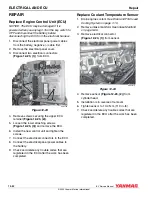
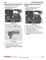
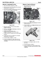
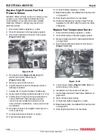
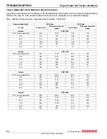
Replace High-Pressure Fuel Rail
Pressure Sensor
NOTICE: When working on the oil, coolant or fuel
systems, you must protect the alternator from
contamination. Cover alternator with suitable
materials. Failure to comply may result in an
alternator failure.
1. Disconnect battery negative (-) cable.
2. Shut off all valves in the fuel supply system.
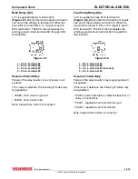
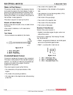
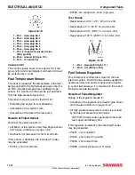
3. Disconnect electrical connector from sensor
(Figure 12-32, (1)).
Figure 12-32
Figure 12-32
4. Hold sensor hex (Figure 12-32, (2)) with
wrench and loosen retaining nut
(Figure 12-32, (3)).
5. Remove sensor from fuel rail.
6. Inspect threads of sensor. Replace sensor if
damage is evident.
7. Inspect the O-ring and replace if necessary.
8. Apply a light coating of petroleum jelly to O-ring.
9. Install sensor in fuel rail. Ensure orientation is
correct. NOTICE: The high-pressure fuel
sensor can be installed a maximum of ten
times. After ten installations, a new sensor must
be installed.
10. Hold hex of sensor and tighten retaining nut to
70 N·m (52 ft-lb).
11. Connect electrical connector to sensor.
12. Open all fuel supply valves.
13. Connect battery negative (-) cable.
14. Bleed fuel system. See Bleed the Fuel System
15. Start engine and check for fuel leaks.
16. Check and delete any trouble codes that are
registered in the ECU after the work has been
completed.
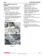
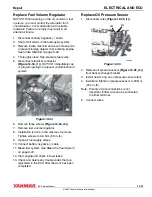
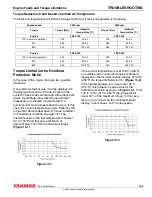
Replace Fuel Temperature Sensor
1. Disconnect the battery negative (-) cable.
2. Shut off all valves in the fuel supply system.
3. Remove intake manifold. See Intake Manifold
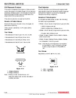
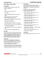
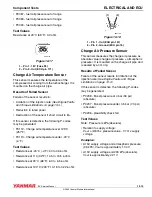
4. Disconnect electrical connector from sensor
(Figure 12-33, (1)).
Figure 12-33
Figure 12-33
5. Loosen hose clamps (Figure 12-33, (2)) and
remove hoses from sensor.
6. Installation is in the reverse of removal.
7. Install intake manifold. See Intake Manifold on
8. Open all fuel supply valves.
9. Connect the battery negative (-) cable.
10. Bleed fuel system. See Bleed the Fuel System
11. Start engine and check for fuel leaks.
000
3
6
83
(1)
(1)
(2)
(1)
(
3
)
000
3
6
88
A
(1)
(2)
Содержание 4BY2
Страница 1: ...BY series SERVICE MANUAL BY Service Manual 4BY2 6BY2 P N 0BBY0 U00200 MARINE ENGINES ...
Страница 10: ...TABLE OF CONTENTS x BY Service Manual 2009 Yanmar Marine International This Page Intentionally Left Blank ...
Страница 46: ...PERIODIC MAINTENANCE 4 2 BY Service Manual 2009 Yanmar Marine International This Page Intentionally Left Blank ...
Страница 132: ...ENGINE Exhaust Manifold 5 70 BY Service Manual 2009 Yanmar Marine International This Page Intentionally Left Blank ...
Страница 134: ...FUEL SYSTEM 6 2 BY Service Manual 2009 Yanmar Marine International This Page Intentionally Left Blank ...
Страница 156: ...COOLING SYSTEM 7 2 BY Service Manual 2009 Yanmar Marine International This Page Intentionally Left Blank ...
Страница 174: ...COOLING SYSTEM Repair 7 20 BY Service Manual 2009 Yanmar Marine International This Page Intentionally Left Blank ...
Страница 176: ...LUBRICATION 8 2 BY Service Manual 2009 Yanmar Marine International This Page Intentionally Left Blank ...
Страница 188: ...TURBOCHARGER 9 2 BY Service Manual 2009 Yanmar Marine International This Page Intentionally Left Blank ...
Страница 194: ...TURBOCHARGER Repair 9 8 BY Service Manual 2009 Yanmar Marine International This Page Intentionally Left Blank ...
Страница 196: ...STARTER MOTOR 10 2 BY Service Manual 2009 Yanmar Marine International This Page Intentionally Left Blank ...
Страница 202: ...ALTERNATOR 11 2 BY Service Manual 2009 Yanmar Marine International This Page Intentionally Left Blank ...
Страница 234: ...ELECTRICAL AND ECU Repair 12 28 BY Service Manual 2009 Yanmar Marine International This Page Intentionally Left Blank ...
Страница 236: ...TROUBLESHOOTING 13 2 BY Service Manual 2009 Yanmar Marine International This Page Intentionally Left Blank ...