background image

2.  Inspection and adjustment

53

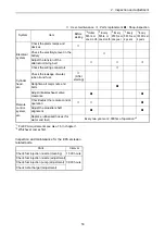
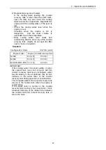
*1 

For EPA requirements see also 1.6 in chapter 1.

*2 

Whichever comes first. 

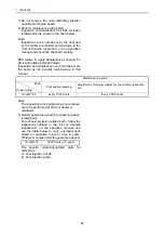
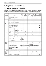
Inspection and maintenance for the EPA emission

related parts.

{

 : User-maintenance  

Å

 : Parts replacement  

z

 : Shop-inspection

System

Item

Before 
starting

*2

 Initial 

50hrs. or 
one month

*2

 Every 

50hrs. or 
one month

*2

 Every

250 hrs. or 
one year

*2

 Every

500 hrs. or 
2 years

*2

 Every

1000 hrs. or 
4 years

Electrical 
system

Check the alarm lamps and 
devices

{

Check the electrolyte level in the 
battery

{

Adjust the tension of the 
alternator driving belt

{

{

Å

Check the wiring connectors

{

Cylinder 
head,
etc.

Check the leakage of water, 
lube oil and fuel.

{

(After 

starting)

Retighten all major nuts and 
bolts

z

Adjust intake/exhaust valve 
clearance

z


z

Remote 
control
system, 
etc.

Check/adjust the remote control 
operation

{

{

z

Adjust the propeller shaft 
alignment

z

z

Replace rubberized hoses (for 
water and fuel)

Every two years or 2,000hrs of operation *

2


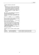
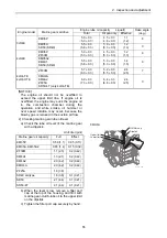
Parts

Interval

Check fuel injection nozzle (cleaning)

1,500 hours

Check fuel injection nozzle (adjustment)

3,000 hours

Check fuel injection pump (adjustment)

Check turbocharger (adjustment)

Содержание 3JH4E

Страница 1: ......

Страница 2: ......

Страница 3: ...Outline of correction Correction item No page Corrected by New edition February 2004 Aug 2006 Adding 4JH4 TE 4JH4 HTE 4JH4 TE and 4JH4 HTE added Manual code M9961 03E091 was changed to 0BJH4 G00100 3 4JH4E alternator standard Page 4 5 304 308 Marine Business Development Dept R1 Jan 2007 Correction the procedure of measurement and adjustment of intake and exhaust valves Page 63 67 YMI Business Deve...

Страница 4: ......

Страница 5: ...engine itself To get maximum performance from this engine you should completely understand its functions construction and capabilities as well as proper use and servicing Use this manual as a handy reference in daily inspection and maintenance and as a text for engineering guidance Model 3JH4E and 4JH4 TE have been used for the illustrations in this service manual but they apply to other models in...

Страница 6: ......

Страница 7: ...2 2 1 Check before starting 54 2 2 2 Inspection after initial 50 hours or one month operation 60 2 2 3 Inspection every 50 hours or monthly 69 2 2 4 Inspection every 250 hours or one year 74 2 2 5 Inspection every two years 84 2 2 6 Inspection every 1 000 hours or four years 84 2 3 Adjusting the no load maximum or minimum speed 94 2 4 Sensor inspection 95 2 4 1 Oil pressure switch 95 2 4 2 Thermo ...

Страница 8: ...ly 156 5 Inspection and servicing of basic engine parts 175 5 1 Cylinder block 175 5 1 1 Inspection of parts 175 5 1 2 Cleaning of oil holes 175 5 1 3 Color check procedure 176 5 1 4 Replacement of cup plugs 177 5 1 5 Cylinder bore measurement 178 5 2 Cylinder head 179 5 2 1 Inspecting the cylinder head 181 5 2 2 Valve seat correction procedure 182 5 2 3 Intake exhaust valves valve guides 184 5 2 ...

Страница 9: ... 215 6 1 1 Fuel system diagram 215 6 1 2 Fuel injection pump service data 216 6 1 3 Fuel injection pump structure 219 6 1 4 Removing a fuel injection pump 220 6 1 5 Installing a fuel injection pump 221 6 1 6 Adjusting fuel injection timing 221 6 1 7 Troubleshooting of fuel injection pump 221 6 1 8 Tools 222 6 2 Fuel feed pump 224 6 2 1 Construction of fuel feed pump 224 6 2 2 Fuel feed pump specif...

Страница 10: ...spection only for 3JH4E and 4JH4E 244 7 2 Exhaust system 245 7 2 1 Exhaust system for 3JH4E and 4JH4E 245 7 2 2 Exhaust system for 4JH4 TE and 4JH4 HTE 246 7 2 3 Mixing elbow inspection 246 7 3 Turbocharger 247 8 Lubrication system 252 8 1 Lubrication system 252 8 2 Lube oil pump 253 8 2 1 Lube oil pump construction 253 8 2 2 Specifications of lube oil pump 253 8 2 3 Lube oil pump disassembly and ...

Страница 11: ...ons of heat exchanger 271 9 4 3 Disassembly and reassembly of the heat exchanger 271 9 4 4 Heat exchanger inspection 272 9 5 Pressure cap and coolant recovery tank 273 9 5 1 Pressure cap construction 273 9 5 2 Pressure cap pressure control 273 9 5 3 Pressure cap inspection 273 9 5 4 Replacing filler neck 274 9 5 5 Function of the coolant recovery tank 275 9 5 6 Specifications of coolant recovery t...

Страница 12: ...control system 290 11 1 2 Remote control device components 290 11 2 Remote control installation 292 11 3 Remote control inspection 295 11 4 Remote control adjustment 296 12 Electrical system 297 12 1 Electrical system 297 12 1 1 Wiring diagram 298 12 2 Battery 300 12 3 Starting motor 301 12 3 1 Specifications 301 12 3 2 Characteristics 301 12 3 3 Structure 302 12 3 4 Wiring diameter of a starting ...

Страница 13: ... oil pressure gauge 313 12 7 3 Coolant temperature alarm 314 12 7 4 Sender unit for the coolant temperature gauge 314 12 8 Air heater Optional 315 12 9 Electric engine stopping device 316 13 Service standards 317 13 1 Engine tuning 317 13 2 Engine body 319 13 2 1 Cylinder head 319 13 2 2 Camshaft and gear train 321 13 2 3 Cylinder block 322 13 3 Lubricating oil system Trochoid pump 326 14 Tighteni...

Страница 14: ......

Страница 15: ...nce in the manual Sufficient consideration for safety is required in addition to the matters marked Especially for safety precautions in a repair or maintenance job not described in this manual receive instructions from a knowledgeable leader Safety marks used in this manual and their meanings are as follows DANGER indicates an imminent hazardous situation which if not avoided WILL result in death...

Страница 16: ...ll type accidents Clean orderly arranged place No dust mud oil or parts should be left on the floor surface Failure to Observe An unexpected accident may be caused Bright Safely Illuminated Area The work area should be well lit or illuminated in a safe manner For work in enclosed or dark areas a drop cord should be utilized The drop cord must have a wire cage to prevent bulb breakage and possible ...

Страница 17: ...ap as an attaching device Do not use rope serious injury may result To hold or support an engine secure the engine to a support stand test bed or test cart designed to carry the weight of the engine Do not overload this device serious injury may result Never run an engine without being properly secured to an engine support stand test bed or test cart serious injury may result Appropriate Tools Alw...

Страница 18: ...of ignition away Explosion may occur causing severe personal injury Battery Electrolyte Batteries contain sulfuric acid Do NOT allow it to come in contact with clothing skin and or eyes severe burns will result 7 WASTE MANAGEMENT Observe the following instructions with regard to hazardous waste disposal Negligence of these will have a serious impact on environmental pollution concerns 1 Waste flui...

Страница 19: ...lothing jewelry ties or tools may become entangled causing damage to the engine and or severe personal injury Preventing burns from scalding 1 Never open the filler cap shortly after shutting the engine down Steam and hot water will spurt out and seriously burn you Allow the engine to cool down before attempt to open the filler cap 2 Securely tighten the filler cap after checking the coolant Steam...

Страница 20: ...ed check the part installed state deformation damage roughening surface defect etc Arrange the removed parts orderly with clear distinction between those to be replaced and those to be used again Parts to be used again shall be washed and cleaned sufficiently Select especially clean locations and use clean tools for disassembly of hydraulic units such as the fuel injection pump 5 Precautions for I...

Страница 21: ...lter 9 Fuel filter 2 Shift lever 6 Fuel feed pump 10 Dipstick 3 Marine gear 7 Oil filter cap 11 Intake manifold 4 Oil cooler 8 Fuel injection pump 1 Coolant filler cap 4 Starter motor 7 Alternator 2 Engine name plate on the rocker arm cover 5 Exhaust mixing elbow 8 Coolant tank Heat exchanger 3 Seawater pump 6 Exhaust manifold 1 4 5 6 7 8 9 10 11 2 3 010297 01X 1 2 3 4 5 6 7 8 010298 01X ...

Страница 22: ... Turbocharger 6 Lube oil filter 10 Dipstick 3 Shift lever 7 Fuel injection pump 11 Intake manifold 4 Marine gear KMH4A 8 Fuel filter 12 Oil filler cap 1 Engine name plate on the rocker arm cover 4 Seawater pump 7 Exhaust mixing elbow 2 Coolant filler cap 5 Alternator 8 Coolant tank Heat exchanger 3 Belt cover 6 Starter motor 12 11 9 10 8 7 6 5 4 3 2 1 008831 01X 1 2 8 5 7 6 4 3 008832 01X ...

Страница 23: ...harger 6 Lube oil filter 10 Dipstick 3 Shift lever 7 Fuel injection pump 11 Intake manifold 4 Marine gear KMH4A 8 Fuel filter 12 Oil filler cap 1 Engine name plate on the rocker arm cover 4 Seawater pump 7 Starter motor 2 Coolant filler cap 5 Alternator 8 Exhaust mixing elbow 3 Belt cover 6 Intercooler 9 Coolant tank Heat exchanger 12 11 9 10 8 7 6 5 4 3 2 1 008392 01X 1 2 9 5 8 7 6 4 3 008393 01X...

Страница 24: ...at propeller shaft Engine speed kW HP min 1 28 0 38 1 3000 at Fuel temp 25 C 27 4 37 3 3000 at Fuel temp 40 C Installation Flexible mounting Fuel injection timing deg b T D C FID 12 1 FIC Air 13 1 Fuel injection opening pressure MPa kgf cm2 21 6 0 5 220 5 Main power take off At flywheel side Direction of rotation Crankshaft Counter clockwise viewed from stern Propeller shaft Ahead Clockwise viewed...

Страница 25: ...C 39 6 53 8 3000 at Fuel temp 40 C Output at propeller shaft Engine speed kW HP min 1 38 5 52 3 3000 at Fuel temp 25 C 37 6 51 1 3000 at Fuel temp 40 C Installation Flexible mounting Fuel injection timing deg b T D C FID 13 1 FIC Air 14 1 Fuel injection opening pressure MPa 21 6 0 5 Main power take off At flywheel side Direction of rotation Crankshaft Counter clockwise viewed from stern Propeller ...

Страница 26: ... 65 0 69 Lubricating oil capacity effect 0 05 0 05 0 15 0 16 0 15 0 16 Cooling system Air cooling by fan on flywheel Mass kg 12 13 13 Marine gear or sail drive Model ZF30M kM4A1 SD50 coupled at boat builder Type Mechanical multi plate clutch Mechanical cone clutch Reduction ratio Forward Reverse 2 15 2 64 2 70 2 64 1 47 1 47 2 14 2 14 2 63 2 63 3 30 3 30 2 32 Propeller speed Forward Reverse min 1 ...

Страница 27: ...HP min 1 53 0 72 1 3200 at Fuel temp 40 C Installation Flexible mounting Fuel injection timing deg b T D C Plunger lift at Top Dead Center 1 26 0 01mm when W C S D is released FIT at plunger lift 1 00mm with W C S D released 2 55 1 Fuel injection opening pressure MPa 21 6 0 5 Main power take off At flywheel side Direction of rotation Crankshaft Counter clockwise viewed from stern Propeller shaft A...

Страница 28: ... speed kW HP min 1 1 77 7 106 3200 Installation Flexible mounting Fuel injection timing deg b T D C Plunger lift at Top Dead Center 1 26 0 01mm when W C S D is released FIT at plunger lift 1 00mm with W C S D released 2 55 1 Fuel injection opening pressure MPa 21 6 0 5 Main power take off At flywheel side Direction of rotation Crankshaft Counter clockwise viewed from stern Propeller shaft Ahead Cl...

Страница 29: ...n ratio Forward Reverse 2 15 2 64 2 70 2 64 1 47 1 47 2 14 2 14 2 63 2 63 2 04 2 04 2 45 2 45 1 93 1 93 2 48 2 48 2 32 Propeller speed Forward Reverse min 1 1444 1176 1150 1176 2115 2113 1451 1450 1180 1179 1520 1520 1263 1263 1607 1607 1250 1250 1337 Lubrication system Splash Centrifugal pump Trochoid pump Trochoid pump Oil bath Lube oil ATF API CD or higher SAE 20 or 30 ATF QuickSilver High Perf...

Страница 30: ...r A2 for UK JIS K2204 for JAPAN The following requirements also need to be fulfilled Cetane number should be equal to 45 or higher Sulphur content of the fuel It should not exceed 0 5 by volume Preferably it should be below 0 05 Water and sediment in the fuel oil should not exceed 0 05 by volume Ash should not exceed 0 01 by mass 10 carbon residue content of the fuel It should not exceed 0 35 by v...

Страница 31: ...n water and dust Before supplying fuel let the fuel container rest for several hours so that water and dust in the fuel are deposited on the bottom Pump up only the clean fuel 3 Fuel tank Be sure to attach a drain cock precipitation trap and primary strainer to the fuel tank as shown illustration right 011213 00X Sediment trap Drain cock To engine Fuel pipe To engine 010156 00E ...

Страница 32: ...F oil to marine gear ZF30M for 4JH4E and ZF30N ZF25A for 4JH4 TE and 4JH4 HTE 3 Selection of lube oil for sail drive unit SD50 or SD40 for 3JH4E and 4JH4E API service grade GL4 5 SAE Viscosity 90 or 80W90 or QuickSilver High Performance Gear Lube QuickSilver is registered trademark of Brunswick Corporation SD50 4T for 4JH4 TE QuickSilver High Performance Gear Lube must be selected only for SD50 4T...

Страница 33: ... mixing ratio of antifreeze to fresh water strictly as instructed by the antifreeze maker If too much antifreeze is used the cooling performance of the coolant will drop and the engine may become overheated 6 Do not mix different brands of antifreeze Chemical reactions may make the antifreeze useless and engine trouble could result Excessive use of antifreeze also lowers the cooling efficiency of ...

Страница 34: ...1 General 14 1 4 Engine outline 1 3JH4E with KM35P marine gear 010300 00E ...

Страница 35: ...1 General 15 2 3JH4BE with KM35A marine gear 010301 00E ...

Страница 36: ...1 General 16 3 3JH4CE with SD50 SD40 sail drive 011211 00E ...

Страница 37: ...1 General 17 4 3JH4ME Bobtail 011745 00E ...

Страница 38: ...1 General 18 5 4JH4E with KM35P marine gear 010303 00E ...

Страница 39: ...1 General 19 6 4JH4FE with ZF30M marine gear 010304 00E ...

Страница 40: ...1 General 20 7 4JH4BE with KM35A2 marine gear 010305 00E ...

Страница 41: ...1 General 21 8 4JH4B4E with KM4A1 marine gear 010306 00E ...

Страница 42: ...1 General 22 9 4JH4CE with SD50 SD40 sail drive 011212 00E ...

Страница 43: ...1 General 23 10 4JH4ME Bobtail 011746 00E ...

Страница 44: ...1 General 24 11 4JH4 TFE with ZF30M marine gear 010308 00E ...

Страница 45: ...1 General 25 12 4JH4 TBE with KM4A2 marine gear 010309 00E ...

Страница 46: ...1 General 26 13 4JH4 THE with KMH4A marine gear 010310 00E ...

Страница 47: ...1 General 27 14 4JH4 TIE with ZF25A marine gear 010311 00E ...

Страница 48: ...1 General 28 15 4JH4 TCE with SD50 4T sail drive 010312 00X ...

Страница 49: ...1 General 29 16 4JH4 HTFE with ZF30M marine gear B 010313 00E ...

Страница 50: ...1 General 30 17 4JH4 HTBE with KM4A2 marine gear 010314 00E ...

Страница 51: ...1 General 31 18 4JH4 HTHE with KMH4A marine gear 010315 00E ...

Страница 52: ...1 General 32 19 4JH4 HTIE with ZF25A marine gear 010316 00E ...

Страница 53: ...1 General 33 1 5 Piping diagrams 1 3JH4 B E Note The following piping diagram is for the 3JH4 B E model 010317 00X ...

Страница 54: ...1 General 34 2 3JH4CE with SD50 SD40 sail drive 015032 00E ...

Страница 55: ...1 General 35 3 4JH4 B E with KM35P KM35A2 marine gear 015033 00E ...

Страница 56: ...1 General 36 4 4JH4B4E with KM4A1 marine gear 015034 00E ...

Страница 57: ...1 General 37 5 4JH4FE with ZF30M marine gear 015035 00E ...

Страница 58: ...1 General 38 6 4JH4CE with SD50 SD40 sail drive 015036 00E ...

Страница 59: ...1 General 39 7 4JH4 TE with KM4A2 marine gear 015037 00E ...

Страница 60: ...1 General 40 8 4JH4 TE with KMH4A and ZF25A marine gear 015038 00E ...

Страница 61: ...1 General 41 9 4JH4 TE with ZF30M marine gear 015039 00E ...

Страница 62: ...1 General 42 10 4JH4 TE with SD50 4T sail drive 015040 00E ...

Страница 63: ...1 General 43 11 4JH4 HTE with KM4A2 marine gear 010327 00E ...

Страница 64: ...1 General 44 12 4JH4 HTE with KMH4A and ZF25A marine gear 010328 00E ...

Страница 65: ...1 General 45 13 4JH4 HTE with ZF30M marine gear 010329 00E ...

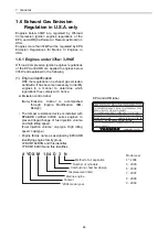
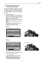
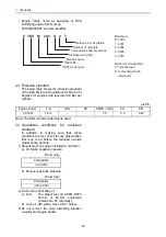
Страница 66: ...mper resistance device is installed with EPA ARB certified 3JH4E series engines to prevent illegal change of fuel injection volume and high idling speed Fuel injection volume cap type High idling speed cap type Engine family name as assigned by EPA ARB identifying engine family group 4YDXM1 64D3N and this identifies YYDXM1 64D3N and this identifies IMPORTANT ENGINE INFORMATION ENGINE MODEL 3JH4E E...

Страница 67: ...ng sure that these conditions are met check for any deterioration that may occur before the required periodic maintenance times 1 Requirement on engine installation condition a Air intake negative pressure b Exhaust gas back pressure 2 Fuel oil and lubricating oil a Fuel Diesel fuel oil ASTM D975 No 1 D or No 2 D equivalent Cetane No 45 minimally b Lube oil API grade class CD g kWh g HPhr Engine p...

Страница 68: ...maintenance in this manual Note The inspection and maintenance shown above are to be performed at Yanmar dealer or distributor 5 Quality guarantee period for exhaust emission related parts For exhaust emission related parts follow the inspections outlined in the List of Periodic Inspections on the operation manual and use the table below to carry out inspections based on operation hours or time in...

Страница 69: ...GINE EMISSION CONTROL INFORMATION REFER TO OWNER S MANUAL FOR MAINTENANCE SPECIFICATIONS AND ADJUSTMENTS ENGINE FAMILY 6YDXM2 00D4T APPLICATION COMMERCIAL THIS ENGINE COMPLIES TO U S EPA REGULATIONS 40 CFR PART 94 WHICH APPLY TO MARINE ENGINES DISPLACEMENT PER CYLINDER 0 499 LITERS STANDARDS THC NOx 7 5g kWh CO 5 0g kWh PM 0 40g kWh MODEL YEAR 2006 ENGINE MODEL 4JH4 TE YANMAR CO LTD EPA label 0117...

Страница 70: ...ement on engine installation condition a Air intake negative pressure b Exhaust gas back pressure 2 Fuel oil and lubricating oil a Fuel The diesel fuel oil ASTM D975 No 1 D or No 2 D equivalent Cetane No 45 minimally b Lube oil API grade class CD or higher 3 Do not remove the caps restricting injection quantity and engine speed g kWh Engine Power Tier NOx HC NMHC NOx CO PM º 37kW Tier 2 7 5 5 0 0 ...

Страница 71: ... maintenance in this manual These must be performed to keep the emission values of the engine in the standard values during the warranty period The warranty period is determined by the age of the engine or the number of hours of operation Refer to the Warranty statement attached to the operation manual Warranty period for exhaust emission related parts Parts Interval Check fuel injection nozzle cl...

Страница 72: ...ck the fuel level and refill Drain the fuel tank Drain the fuel water separator Replace the fuel filter Å Check the injection timing z Check the injection spray condition z 1 Lubricating system Check the lube oil level Crankcase Marine gear Replace the lube oil Crankcase Å Å Marine gear Å Å Replace the lube oil filter Engine Å Å Marine gear Å Å Cooling system Seawater outlet During operation Check...

Страница 73: ... electrolyte level in the battery Adjust the tension of the alternator driving belt Å Check the wiring connectors Cylinder head etc Check the leakage of water lube oil and fuel After starting Retighten all major nuts and bolts z Adjust intake exhaust valve clearance z z Remote control system etc Check adjust the remote control operation z Adjust the propeller shaft alignment z z Replace rubberized...

Страница 74: ...Crankcase Marine gear 1 Checking engine lube oil level a Check the lube oil level of a engine with a dipstick Insert the dipstick fully and check the oil level The oil shall not be contaminated heavily and have appropriate viscosity No cooling water or diesel fuel shall be mixed Standard The level shall be between the upper and lower limit lines on the dipstick b If the remaining engine oil level ...

Страница 75: ...model Marine gear sail drive Engine lube oil capacity L quart Rake angle deg Total Oil pan only Effective 3JH4E KM35P 5 0 0 3 5 3 0 3 4 5 0 3 4 8 0 3 1 1 1 2 8 KM35A SD50 SD40 5 5 0 3 5 8 0 3 5 0 0 3 5 3 0 3 1 2 1 3 0 4JH4E KM35P ZF30M 5 0 0 3 5 3 0 3 4 5 0 3 5 3 0 3 1 2 1 3 8 KM35A2 KM4A1 SD50 SD40 5 5 0 3 5 8 0 3 5 0 0 3 5 3 0 3 1 4 1 5 0 4JH4 TE 4JH4 HTE ZF30M 5 7 0 3 6 0 0 3 5 2 0 3 5 5 0 3 2 ...

Страница 76: ...is cooled down after the engine stopped wrap the filler cap with a rag piece and turn the cap slowly to gently release the pressure inside the flesh water tank Securely tighten the filler cap after checking the flesh water tank If the cap is tightened loosely steam can spurt out during operation 1 Checking cooling water volume Check the cooling water level in the coolant recovery tank If the water...

Страница 77: ...heck or replenish Standard IMPORTANT If the cooling water runs short quickly or when the coolant tank runs short of water with the coolant recovery tank level unchanged water may be leaking or the air tightness may be lost Increase in the water level of the coolant recovery tank during operation is not abnormal The increased water in the coolant recovery tank returns to the coolant tank when the e...

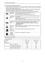
Страница 78: ...ature alarm When the temperature reaches the maximum 95 C 203F or higher the lamp will light Continuing operation at temperatures exceeding the maximum limit will result in damage and seizure Check the load and the fresh water cooling system for any abnormalities Lubricating oil low pressure alarm When the lubricating oil pressure falls below normal the oil pressure sensor will register this and t...

Страница 79: ...so check the leakage of lube oil and fuel 8 Check adjust the remote control operation Make sure that the accelerator of a boat can be operated smoothly before starting the engine If it feels heavy to manipulate lubricate the accelerator cable joints and pivots Adjust the accelerator cable if there is a dislocation or excessive play between the accelerator and the governor lever ...

Страница 80: ...ly contaminated due to the initial wear of internal parts The lube oil must therefore be replaced early It is easiest and most effective to drain the engine lubricating oil after operation while the engine is still warm Replace the lube oil filter at the same time Beware of oil splashes if extracting the lube oil while it is hot No Inspection item 1 Drain the fuel tank 2 Replace the engine lube oi...

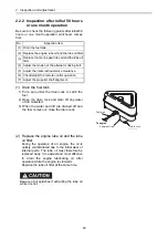
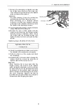
Страница 81: ...ing surface and tighten it further to 3 4 of a turn with the filter wrench Tightening torque 20 24Nm 177 212 lb in 4 Fill with new lubricating oil Refer to 2 2 1 3 for the standard of the engine lube oil capacity 5 Perform a trial run of the engine and check the oil leakage 6 Approximately 10 minutes after stopping the engine check the oil level by using the oil dipstick Add oil if the level is to...

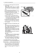
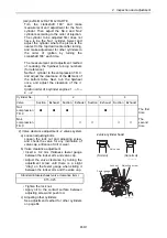
Страница 82: ...e alternator drive belt When there is not enough tension in the V belt it will slip and the cooling water pump will fail to supply cooling water Engine over heating and the seizure will occur When there is too much tension in the V belt the belt will become damaged more quickly and the bearing of the cooling water pump may be damaged Check and adjust the V belt tension deflection in the following ...

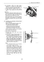
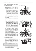
Страница 83: ...th systems clearance can be adjusted by the screw on the rocker arm 1 Valve clearance measurement a Remove the rocker arm cover above cylinder head b Set the No 1 cylinder Flywheel side in the compression Top Dead Center TDC Turn the crankshaft to bring the piston of the No 1 cylinder to its compression top dead center while watching the rocker arm motion the timing mark of the flywheel housing an...

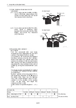
Страница 84: ...nearest to the top dead center after turning and make measurement and adjustment for other cylinders in the order of ignition by turning the crankshaft 240 each time The measurement and adjustment method of reducing the flywheel turning numbers for reference Set No 1 cylinder to the compression T D C and adjust the clearance of the z mark of the below table Next turn the flywheel once the suction ...

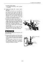
Страница 85: ...r engines 1 3 4 2 2 Valve clearance adjustment 2 valves system a Loosen adjusting bolts Loosen the lock nut and adjusting screw and check the valve for any inclination of valve cap entrance of dirt or wear b Valve clearance adjustment Insert a 0 2 mm thickness feeler gauge between the rocker arm and valve cap Adjust the valve clearance by turning the adjustment screw until there is a slight drag o...

Страница 86: ...he valve bridge has equal contact with the front and rear valves apply light pressure hold by rocker arm screw in rocker arm adjusting screw until rocker arm touches the valve bridge Adjust the valve bridge adjusting screw so there is zero 0 clearance between the adjustment screw and the front valve Tighten the locknut while holding the valve bridge with a wrench Verify that the valve bridge clear...

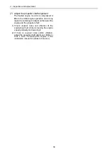
Страница 87: ...trol lever is moved to H high speed and L low speed respectively When there is deviation loosen the bracket for the remote control cable on the engine side and adjust Adjust the high speed stop position first and then adjust the low speed idling by the adjustment bolt on the remote control lever Never adjust the high speed limiting bolt This will void warranty 2 Adjusting the marine gear remote co...

Страница 88: ...use the centering misalignment between the engine and the propeller shaft 1 Check unusual noise and vibration of the engine boat hull while increasing the engine speed gradually and lowering it 2 If there is unusual noise and or vibration adjust the propeller shaft alignment Refer to Part I 6 4 5 Centering the engine in the installation manual for pleasure boat use ...

Страница 89: ...omes out of the bolt hole tighten the air bleeding bolt 3 Loosen the air bleeding bolt of the fuel filter by turning it 2 or 3 turns 4 Feed fuel with the fuel feed pump by moving the lever on the left side of the feed pump up and down 5 Allow the fuel containing air bubbles to flow out from the air bleeding bolt hole When the fuel no longer contains bubbles tighten the air bleeding bolt This compl...

Страница 90: ...e fuel tank 5 Tighten the drain plug 6 Remove the drain tube 7 Install the fire resistant cover and tighten the hose clamp 8 Bleed air from the fuel system When there is a heavy deposit drain the fuel tank at the same time Fuel system air bleeding procedures 1 Check the fuel level in the fuel tank Replenish if Insufficient 2 Open the fuel cock of the fuel tank 3 Loosen the air bleeding bolt on the...

Страница 91: ...ect the Negative battery cable back onto the battery LAST Proper ventilation of the battery area Keep the area around the battery well ventilated paying attention to keep away any fire source During operation or charging hydrogen gas is generated from the battery and can be easily ignited Do not come in contact with battery electrolyte Pay sufficient attention to avoid your eyes or skin from being...

Страница 92: ...e unit after daily use if letting the machine unit leave in the place that the ambient temperature could drop at 15 C or less And store the battery in a warm place until the next use the unit to start the engine easily at low ambient temperature 2 Battery charge Use a battery tester or hydrometer and check the battery condition If the battery is discharged recharge it a Measurement with a battery ...

Страница 93: ...fic gravity and remaining battery charge 3 Terminals Clean if corroded or soiled 4 Mounting bracket Repair or replace it if corroded Retighten if loosened 5 Battery appearance Replace the battery if cracked or deformed Clean with fresh water if contaminated Specific gravity 20 C Discharged quantity of electricity Remaining charge 1 28 0 100 1 26 10 90 1 24 20 80 1 23 25 75 011220 00X Float 011218 ...

Страница 94: ...of rag to prevent the fuel oil from dropping 3 Clean the filter mounting surface and slightly apply fuel oil to the gasket of the new fuel filter 4 Install the new fuel filter manually turning until it comes into contact with the mounting surface and tighten it further to one turn using a filter wrench Tightening torque 20 24Nm No Inspection item 1 Drain the fuel tank 2 Replace the fuel filter 3 R...

Страница 95: ... the fuel filter with new one Tighten the new fuel filter Part No of the fuel filter 129574 55800 Install the alarm switch to the new fuel filter Apply fuel oil to the gasket of the new fuel filter Lightly screw in the fuel filter in position and tighten it by hand until the gasket comes into contact with the seat After tightening by hand use the filter wrench to tighten it about 3 4 of a turn Tig...

Страница 96: ...er and wear plate If necessary replace with new one and reassemble the side cover Impeller blades are cracked or nicked Edges or surfaces of the blades are marred or scratched Note The impeller must be replaced periodically every 1000 hrs or four years whichever comes first Wear plate is damaged 5 If a large amount of water leaks continuously from the water drain pipe beneath the seawater pump dur...

Страница 97: ...C is used of the specified type the replacement period of two years can be obtained Use clean soft water and be sure to add the Long Life Coolant Antifreeze LLC to the cooling water in order to prevent rust built up and freezing Cooling performance drops when coolant is contaminated with rust and scale Even if antifreeze or antirust is added the coolant must be replaced periodically because the pr...

Страница 98: ...side cover of seawater pump and 1 cock on clutch cooler Note1 4JH4 HTE 3 cocks 3 places a side cover of seawater pump and 2 cocks on clutch cooler and intercooler Note1 Drain cocks for fresh water Drain seawater from seawater pump cover Fresh water pump Coolant tank 015029 00E 4JH4 TE Fuel pump Clutch cooler Drain cock for fresh water Drain cock for seawater 015030 00E Coolant tank Fresh water pum...

Страница 99: ...kwise 1 3 of a turn Coolant tank Fresh water pump Drain cock for seawater Intercooler Drain seawater from seawater pump cover Drain cocks for fresh water 008792 00J Drain cock for fresh water Drain cock for seawater Fuel pump Clutch cooler 008793 00J 4JH4 HTE Tabs Filler cap Fresh water cooler Notches 008411 01E ...

Страница 100: ...gn the tabs on the bottom of the cap with the notches on the filler port and turn clockwise 1 3 of a turn 6 Remove the coolant recovery tank cap and fill with coolant mix to the lower limit Replace the cap to the coolant recovery tank Coolant recovery tank capacity 0 8L 1 7 pints 7 Check the rubber hose connecting the coolant recovery tank to the fresh water cooler Be sure the hose is securely con...

Страница 101: ... is no improvement after washing the blower repeat the washing process several times NOTICE Do not pour in a large amount of blower wash at one time pour it in gradually as this can damage the blower blades and get water hammer in the combustion chamber leading to accidents 8 Clean the exhaust water mixing elbow There are two types of mixing elbows the L type and the U type The mixing elbow is att...

Страница 102: ...ely dry 10 Adjust the tension of the alternator driving belt Refer to 2 2 2 4 for the procedure 11 Retighten all major nuts and bolts After long time usage the nuts and bolts used may loosen Check and retighten the nuts and bolts such as a Flexible engine mount bolts b Shaft coupling bolts c Exhaust flange bolts d Intake silencer fasteners e Other nuts and bolts Retighten the major nuts and bolts ...

Страница 103: ...l drive Flywheel housing Starting motor Optional Starter S terminal Starter B terminal Fitting to marine gear Battery switch Battery S T O P S T A R T O N O F F 20 30 40 10 50 0 G L O W Alternator Optional Optional Optional Air heater Intake manifold C W temp sensor C W temp switch Relay Stop solenoid Earth bolt Extension wire harness Magnetic relay Safety relay 010625 00E ...

Страница 104: ...and gear case are aligned 3 Set the speed control lever at the operating position 4 Disconnect the injection pipe on the fuel pump side for the No 1 cylinder Do not remove the delivery holder 5 Check the fuel discharge from the delivery holder while turning the crankshaft clockwise as seen from the gear case side and stop turning it at the same time when the fuel comes out Wipe out the fuel of the...

Страница 105: ... the fuel injection pump toward or away from the engine for adjustment Incline toward the engine to delay the timing and away from the engine to advance it 4JH4 TE and 4JH4 HTE The fuel injection timing is adjusted so that engine performance may become the best condition and comply with the emission regulations This VE pump equips W C S D Wax type Cold Start Device which improves the startability ...

Страница 106: ...n the C S D lever to turn the lever for canceling W C S D While turning the C S D lever to the left insert the spacer at the top of wax pellet Thickness of the spacer is 7 5 0 1mm at the room temperature of 0 30 degrees C when engine is cold A B C 010426 00X mm A B C 95 5 M8 x 1 0 ø4 Dial gage CSD lever Plug 010424 00E Wax pellet Spacer C S D lever Screw driver 010423 00E ...

Страница 107: ... lift Check the minimum value is set to 0 by turning the crankshaft right and left 4 Turn the crankshaft slowly to the engine rotating direction counterclockwise viewed from stern and set the crankshaft to the compression top dead center 5 Check the dial gage If the plunger lift comes off the standard value loosen the 5 nuts about 90 degrees which fix the VE pump bracket to a gear case flange The ...

Страница 108: ...ssure of the brand new fuel nozzle about 0 5 MPa 5 kgf cm declines by the engine operation for about 5 hours because of the initial wear out of a spring etc Therefore adjust 0 5 MPa 5 kgf cm higher than the standard value of the above table when adjusting a new fuel nozzle of a spare part Remove carbon deposit at the nozzle hole thoroughly before measurement a Connect the fuel injection valve to t...

Страница 109: ...mes increase the pressure gradually Hold the pressure for about 5 seconds at a little before the valve opening pressure of 1 96 MPa 20 kgf cm2 and check to see that oil does not drip from the tip end of the nozzle If extreme oil leak from the overflow joint exists during injection by the nozzle tester check after retightening If much oil is leaking replace the nozzle assembly 010628 00E 010353 00E...

Страница 110: ...lean diesel oil or the like to clean the inner and outer surfaces and to thoroughly remove rust preventive oil before using the nozzle Note that a new nozzle is coated with rust preventive oil and is pasted with the seal peel to shut off outer air 3 Check the impeller of the seawater pump The impeller must be replaced with new one periodically every 1000 hrs or four years whichever comes first Ref...

Страница 111: ...and fresh water inlets and outlets retighten any joints as necessary and clean the insides of the pipes c Check the exhaust gas intake flange and line and replace if corroded or cracked 3 Heat exchanger body water leakage test a Compressed air water tank test Fit rubber covers on the fresh water and seawater inlets and outlets Place the heat exchanger in a water tank feed in compressed air from th...

Страница 112: ...nspect the diaphragm assembly on the rocker arm cover only for 3JH4E and 4JH4E 1 Loosen screws remove the diaphragm assembly and check for oil and contaminants between the diaphragm and the cover If oil and contaminants enter into the diaphragm assembly the diaphragm will not operate as designed 2 Inspect the diaphragm rubber and spring for damage If necessary replace with new ones NOTICE 1 When a...

Страница 113: ...e engine mounts is lost after many hours use This leads to a drop in vibration absorption performance and also causes centering misalignment of the propeller shaft Refer to 5 Flexible Engine Mount in the installation manual for pleasure boat use Note Be sure to replace the Yanmar flexible engine mounts every 1000 hours or 4 years whichever comes first 2 After replacing the flexible engine mounts c...

Страница 114: ... speed is out of the standard adjust it by turning the high idle limiting bolt 3 Then set the no load minimum speed by adjusting the low idle limiting bolt Standards Unit min 1 Model No load maximum No load minimum 3JH4E 4JH4E 3325 25 825 25 4JH4 TE 4JH4 HTE 3775 25 75 800 25 010615 00E Remote control cable Fuel injection pump Low speed limiting bolt High speed limiting bolt Control lever Cable jo...

Страница 115: ...perating the engine It is abnormal if circuit is closed 2 4 2 Thermo switch Place the thermo switch in a container filled with antifreeze or oil Heat it while measuring the fluid temperature The switch is normal if the voltameter shows continuity when the fluid temperature is 97 103 deg C Tester probes Oil pressure switch Cylinder block flywheel side 010636 00E Thermometer Hot water Tester probes ...

Страница 116: ...perature is carved on the flange 2 Normally the thermostat should be inspected every 500 hours of operation but it should be inspected whenever the coolant temperature rises abnormally or white smoke is emitted for a long time after engine starting 3 Replace the thermostat every year or 2000 hours of operation whichever comes first Valve opening temperature deg C Full open lift temperature mm 75 0...

Страница 117: ...vide good ventilation in the engine room 2 6 2 Adjusting operation procedure 1 Supply the fuel oil lubricating oil and coolant Note Check the levels of the lube oil and coolant again after test running for about 10 minutes and add as required 2 Start the engine and carry out idling at a low speed 800 to 900 min 1 for a few minutes 3 Run in the engine for about five minutes at the rated speed no lo...

Страница 118: ...ake exhaust valves fuel injection nozzle and cylinder head 3 Do not raise the engine speed abruptly 3 Cruising load operation 1 Do not operate the engine at full load yet but raise the speed gradually for about 10 minutes until it reaches the rated speed 2 Make sure that exhaust gas color and temperature are normal 3 Check the instrument panel and see if the water temperature and oil pressure are ...

Страница 119: ...silencer air cleaner and electric parts with PVC Poly Vinyl Chloride cover to prevent water and dust from depositing or entrance 7 Select a well ventilated location without moisture and dust for storage 8 Perform recharging once a month during storage to compensate for self discharge 9 When storing an engine for long time run the engine periodically according to the following procedure Because the...

Страница 120: ... the engine number Mentioned in the engine label Examine the machine unit name and its number in the same way When was the engine maintained last time How much period and or time has it been used after it was maintained last time What kind of problem was there on the engine last time and what kind of maintenance was done 3 Hear the occurrence phenomenon from the operator of the engine in detail 5W...

Страница 121: ...f trouble in order to save time in determining their cause Begin by checking the most easily identifiable causes of difficulty Where the cause of the difficulty is not readily apparent make a thorough examination of the system from the very beginning proceeding until the point of trouble can be determined While experience is an important factor in pinpointing engine problems careful study and unde...

Страница 122: ...easure 1 Damage to governor spring Replace 2 Sticking of governor sleeve Clean carefully to insure good working order No Cause and effect Countermeasure 1 Loose lube oil pressure adjustment valve Tighten adjustment valve 2 Clogging of lube oil filter Clean 3 Leakage from lube oil safety valve Tighten safety valve 4 Trouble with lube oil pump Remove and repair or replace 5 Relay operation triggered...

Страница 123: ...amaged exhaust union packing Replace 6 Loose pinion screw Tighten firmly 7 Faulty fuel injection pump tappet Disassemble and clean and repair replace No Cause and effect Countermeasure 1 Oil leakage in injection system Check and repair 2 Damaged valve spring Replace 3 Insufficient injection pressure in injection valves Adjust 4 Irregular injection timing Adjust 5 Sticking of injection valves Clean...

Страница 124: ...is clogged Clean 2 Sticking of valve needle Check repair or replace 3 Low injection pressure Adjust 4 Faulty spry condition Check repair or replace 5 Carbon deposit Clean No Cause and effect Countermeasure 1 Clogged filter Clean No Cause and effect Countermeasure 1 Overloading Reduce load 2 Too great a quantity of lube oil Adjust quantity of oil 3 Carbon deposit in suction valves Clean 4 Dirty air...

Страница 125: ...n 10 Poor assembly of low speed valve handle Reassemble 11 Insufficient oil Check for oil leakage and replenish No Cause and effect Countermeasure 1 Clutch slippage due to low oil pressure Review I 1 I 11 2 Clutch slippage due to overloading Reduce load 3 Damaged bearing Replace 4 Too much oil Check oil level and adjust 5 Problem with oil cooler Check water level and adjust 6 Poor quality or inapp...

Страница 126: ...eplace seal 4 Phase slippage Repair link system No Cause and effect Countermeasure 1 Not enough warp in steel plate Replace 2 Damaged holding spring of pipe Replace 3 Lube oil pressure is too high Adjust lube oil adjustment valve 4 Viscosity of lube oil is too high Change oil No Cause and effect Countermeasure 1 Oil leakage Check and repair 2 Clogged lube oil filter Disassemble and clean 3 Damaged...

Страница 127: ...lter Clean 6 Damaged fuel cam Replace 7 Air in fuel injection system Bleed air and prime 8 Faulty operation of adjustment rack Adjust 9 Uneven amount of fuel to cylinders Adjust No Cause and effect Countermeasure 1 Damaged governor bearing Replace 2 Faulty operation of governor link Adjust 3 Sticking of governor sleeve Clean 4 Faulty operation of fuel oil adjustment Disassemble wash and repair No ...

Страница 128: ...ction timing 2 Fuel pressure is too high Adjust standard injection pressure No Cause and effect Countermeasure 1 Excessive quantity of fuel is ejected from fuel pump Adjust pump adjustment rack No Cause and effect Countermeasure 1 Insufficient coolant Check cooling water pump and lap valves 2 Excess piston clearance Replace 3 Excess bearing clearance Replace 4 Poor quality fuel oil Replace with go...

Страница 129: ...tarter coil Replace 6 Worn commutator Undercut and repair or replace 7 Slippage of starter clutch Replace 8 Excessive resistance between battery and starter Replace with thicker or shorter wire 9 Insufficient battery charge Charge No Cause and effect Countermeasure 1 Imperfect priming of fuel oil system Prime well 2 Injection cut off due to faulty governor Adjust 3 Clogging of fuel inlet filter Cl...

Страница 130: ...e 1 Fuel injection pump timing irregular Adjust 2 Loose high pressure fuel pipe Tighten firmly 3 Damaged high pressure fuel pipe Replace 4 Air in high pressure fuel pipe Bleed air No Cause and effect Countermeasure 1 Air leakage from suction exhaust valves Lap valves 2 No tappet clearance Adjust 3 Faulty gasket packing Replace 4 Upper part of cylinder liner worn Replace 5 Worn piston ring Replace ...

Страница 131: ...an 9 Damaged valve spring Replace 10 Faulty supply pump Repair No Cause and effect Countermeasure 1 Clogging of nozzle hole Clean nozzle hole or replace 2 Faulty valve seat Lap or replace 3 Sticking of valve needle Lap or replace 4 Loose high pressure pipe Tighten firmly 5 Worn valve needle Replace 6 Clogging of filter Clean No Cause and effect Countermeasure 1 Damaged governor bearing Replace 2 I...

Страница 132: ...iston ring Disassemble and repair or replace No Cause and effect Countermeasure 1 Early injection Adjust timing to delay injection 2 Late injection Adjust timing to speed injection No Cause and effect Countermeasure 1 Clogging of air filter Clean No Cause and effect Countermeasure 1 Poor quality fuel oil Replace with good fuel oil 2 Clogging of exhaust line Clean 3 Seizure of moving parts Disassem...

Страница 133: ...ure 1 Clogged lube oil filter Clean 2 Lube oil temperature is too high Add cooling water 3 Trouble with lube oil pump Disassemble and repair or replace 4 Loose pressure adjustment valve Tighten adjustment valve 5 Oil leakage from pump safety valve Tighten safety valve 6 Inadequate viscosity of lube oil Change lube oil 7 Insufficient amount of lube oil Add lube oil 8 Faulty pressure gauge Replace N...

Страница 134: ...f returning water 4 Clogging in coolant system Clean 5 Air in coolant Check suction opening 6 Overloading Reduction load No Cause and effect Countermeasure 1 Clogging in coolant system Clean 2 Trouble with cooling water pump Check pump and repair 3 Coolant lift is too great Lessen lift or replace pump 4 Air in coolant Check suction opening 5 Engine outlet not constricted Eliminate causes for high ...

Страница 135: ... Clogged nozzle Clean 12 Clogged exhaust pipe Clean 13 Too high back pressure Clean or change the piping 14 Wrong reading of pressure gage Replace No Cause and effect Countermeasure 1 Exhaust gas leak Carry out remote of T C 2 Failure in fuel injection system a Inspect and adjust the injection timing b Disassemble and inspect the injection pump and repair or replace faulty parts c Disassemble and ...

Страница 136: ...urbine entrance Repair or replace 5 Rapid change in load surging Stabilize the load or replace turbine nozzle No Cause and effect Countermeasure 1 Gas invasion into bearing chamber Repair 2 Clogged seal air path Clean 3 Damaged seal ring Replace 4 Clogged pressure balance path Clean No Cause and effect Countermeasure 1 Uneven cylinder combustion Adjust for uniform combustion 2 Rapid change in load...

Страница 137: ...timing is incorrect 1 The drive gear or belt connections are incorrect 2 The injection pump is incorrectly installed on the engine 3 The roller holder assembly s roller or pin is worn excessively 4 The plunger is worn excessively Repair Repair and adjust injection timing Replace the assembly Replace the distributor assembly 3 The nozzle does not operate 1 The nozzle or nozzle holder is functioning...

Страница 138: ...e delivery valve spring is broken 10 The delivery valve is not sliding properly 11 The nozzle or the nozzle holder is not functioning properly 12 The injection timing is incorrect Clean or replace Inspect and repair Inspect and repair Replace Replace the distributor assembly Replace Repair or replace Repair or replace Replace Repair or replace Inspect and then repair or replace Readjust Insufficie...

Страница 139: ...t is not smooth Readjust or replace Repair or replace Idling is unstable 1 The injection quantities are not uniform the delivery valve is not operating properly 2 The governor s idling adjustment is improperly adjusted 3 The plunger is worn 4 The plunger spring is broken 5 The rubber damper is worn 6 The governor lever shaft pin is worn excessively 7 The feed pump blades are not operating properly...

Страница 140: ...agnose presence of any abnormality in the engine 1 Compression pressure measurement method 1 After warming up the engine remove the fuel injection pipe and valves from the cylinder to be measured 2 Crank the engine before installing the compression gage adapter a Perform cranking with the stop handle at the stop position no injection state b See 4 2 3 2 in Chapter 4 for the compression gage and co...

Страница 141: ...r 2 3 Valve timing Incorrect valve clearance Adjust the valve clearance See 2 2 6 7 in Chapter 2 4 Cylinder head gasket Gas leak from gasket Replace the gasket Retighten the cylinder head bolts to the specified torque See 14 1 in Chapter 14 5 Intake exhaust vale Valve seat Gas leak due to worn valve seat or foreign matter trapping Sticking valve Lap the valve seat See 5 2 2 in Chapter 5 Replace th...

Страница 142: ... and lube oil Close the seacock 2 Reassembly Sufficiently clean and inspect all parts to be assembled Coat sliding and rotating parts with new engine oil when assembling Replace all gaskets and O rings Use a liquid packing agent as necessary to prevent oil water leaks Check the oil and thrust clearances etc of parts when assembling Make sure you use the correct bolt nut washer Tighten main bolts n...

Страница 143: ...m as instructed 4 2 1 General hand tools Name of tool Illustration Remarks Wrench Size 10 x 13 12 x 14 17 x 19 22 x 24 Screwdriver Steel hammer Local supply Copper hammer Local supply Mallet Local supply Nippers Local supply Pliers Local supply Offset wrench Local supply 1 set 001385 00X 001388 00X 001389 00X 001390 00X 001391 00X 001392 00X 001393 00X 001394 00X ...

Страница 144: ...ocal supply File Local supply 1 set Rod spanner for hexagon socket head screws Local supply Size 6 mm 8 mm 10 mm Stariing pliers Hole type Shaft type S 0 H4 H8 S Hole type H Shaft type Local supply Name of tool Illustration Remarks 001395 00X 001396 00X 001397 00X 001398 00X 001399 00X 001400 00X ...

Страница 145: ...ng rod small end bushing insertion extraction tool for 3JH4E 4JH4TE Extraction Connecting rod small end bushing insertion extraction tool for 4JH4 TE 4JH4 HTE Extraction A B C D 006943 01X mm A B C D 12 20 80 25 011221 00X 011222 00X B C A D 010365 00X mm A B C D 25 4 25 7 20 80 28 4 28 7 010364 00X 010363 00X A B C D E F A B C D E F 31 0 2 0 5 80 20 28 0 45 0 48 45 0 5 9 30 001404 00X ...

Страница 146: ...filter case remover Puller A standard for seawater pump impeller Puller A 129671 92110 standard Name of tool Illustration Remarks A B C D 006943 01X mm A B C D 7 5 20 75 11 Tool 008300 00E 001409 00X 007150 00X 008424 04X B A A B M18 x 1 5 M10 length 40 mm 011205 00X M18 x 1 5 threaded A B 015041 00E ...

Страница 147: ...justment of fuel injection timing Spacer 129671 51990 Piston ring compressor Piston ring replacer for removal insertion of piston ring Name of tool Illustration Remarks 008425 01X A B mm A B Around 110 Around 140 011206 00X A B C 010626 00X A B C 150 20 7 5 0 1 Wax pellet Spacer C S D lever Screw driver 010362 00E 007236 00X 001411 00X ...

Страница 148: ...ing tool Rubber cap type Valve lapping powder Feeler gauge Pulley puller Local supply Removing the coupling Name of tool Illustration Remarks 001412 00X 001413 00X 001414 00X 011215 00E Feeler gauge Lock nut Adjusting screw 001416 01E 001417 00X ...

Страница 149: ...r filler neck Tool 1 Press tool 2 for filler neck copper tube Tool 2 Name of tool Illustration Remarks D E F G A B C H 010331 00X mm A B C D E F G H ø35 5 ø27 5 ø25 105 89 1 2 ø40 Chamfer A B F C D E 010332 00E mm A B C D E F ø28 ø24 2 170 30 30 ø30 ...

Страница 150: ... Stem seal insertion for inserting stem seal Fuel nozzle extraction tool Name of tool Illustration Remarks L2 L1 d1 d2 001421 01X L2 L1 L3 d1 d2 d3 001422 02X mm d1 d2 d3 L1 L2 L3 16 2 22 13 5 18 8 65 4 010333 00X Part No 129470 92300 ...

Страница 151: ... Vernier calipers 0 05 mm 0 150 mm Micrometer 0 01 mm 0 25 mm 25 50 mm 50 75 mm 75 100 mm 100 125 mm 125 150 mm Cylinder gauge 0 01 mm 18 35 mm 35 60 mm 50 100 mm Thickness gauge 0 05 2 mm Torque wrench 128 Nm 0 13 kgf m Nozzle tester 0 49 Mpa 0 500 kgf cm2 001423 00X 001432 00X 001425 00X 001426 00X 007235 00X 010640 00X ...

Страница 152: ...o be used at various angles 4 Micrometer Measures the outer diameter of the crank shaft piston piston pin etc 5 Cylinder gauge Measure the inner diameter of the cylinder liner and rod metal 6 Vernier calipers Measures various outer diameter thickness and width 7 Depth micrometer Measures sinking of valves 8 Square Measures distortion in position of springs and perpendicularity of parts 9 V Block M...

Страница 153: ...r Check for leakage in the fresh water system 13 Battery current tester Checks density of antifreeze and charging condition of battery fluid 14 Nozzle tester Checks the shape and pressure of spray emitted from the fuel injection valve at the time of injection 15 Digital thermostat Measures temperature of various parts No Name of tool Use Illustration 001438 00X 001426 00X 001439 00X 001440 00X 007...

Страница 154: ...eflector seal which is placed on the exterior of the revolving shaft High pressure fuel pipe clamp type Measures rotation speed without reference to revolving shaft center or the exterior of the revolving shaft 17 Circuit tester Measure the resistance voltage and continuity of the electric circuit No Name of tool Use Illustration 001443 00X Revolving shaft Reflection mark 001444 00E High pressure ...

Страница 155: ...e of the compression Adapter for direct injection 2 valve head Adapter for direct injection 4 valve head No Name of tool Use Illustration Gauge set code No TOL 97190080 001448 00X Adapter code No 119802 92950 A 010334 00X A 130 Adapter code No 129906 92950 A 010334 00X A 165 ...

Страница 156: ... 100 g Solvent less type silicone base sealant applicable to high temperature areas 50 C to 250 Three Bond TB1212 100 g Silicone base non fluid type thick application possible Adhesive Three Bond TB1401 200 g Prevention of loose bolts gas leakage and corrosion Torque required to loosen bolt 10 to 20 larger than tightening torque Lock tight SUPER TB1324 50 g Excellent adhesive strength locks bolt s...

Страница 157: ...x the solvent with water Just dipping disassembled part into removes scale To shorten removal time stir remover mixture If cleaning performance drops replace remover mixture with new remover mixture Neutralize used mixture and then dispose of it To judge cleaning performance of mixture put pH test paper into mixture If test paper turns red remover mixture is still effective Neutralizer caustic sod...

Страница 158: ...oupling is mounted to the front drive coupling disassemble 10 Remove the flexible mount nut lift the engine and remove it from the engine base Leave the flexible mount attached to the engine base Disassembling an engine in a workshop 1 Drain seawater 1 Open the seawater drain cock s to drain the seawater Note Don t forget to open a drain cock on a clutch cooler for 4JH4E 4JH4 TE and 4JH4 HTE 2 Ope...

Страница 159: ...ump Coolant tank 015029 00E Fuel pump Clutch cooler Drain cock for fresh water Drain cock for seawater 015030 00E 4JH4 TE Coolant tank Fresh water pump Seawater pump Drain cock for fresh water Drain cock for fresh water Drain cock for seawater 015027 00E Flywheel housing Drain cock for fresh water 015028 00E 3JH4E ...

Страница 160: ...se the rubber of the diaphragm cracked only for 3JH4E and 4JH4E 2 Remove the drain plug on the lower part of the case and drain the lube oil from the marine gearbox Note When using a lube oil supply discharge pump place the intake hose in the dipstick guide for the engine or in the oil hole on top of the marine gear case Coolant tank Fresh water pump Drain cock for seawater Intercooler Drain seawa...

Страница 161: ...fer to 2 2 4 12 4 Removing the fuel filter and fuel pipe 1 Remove the fuel pipes fuel filter fuel feed pump fuel filter fuel injection pump and fuel nozzle fuel filter 2 Remove the fuel filter Fuel nozzle Air bleeding bolt To fuel tank Fuel filter Fuel injection pump Fuel feed pump 010392 00E 3JH4E ...

Страница 162: ...he intake silencer rocker arm cover 2 Remove the intake silencer from intake manifold Intake silencer Clamp Clamp Clamp Clamp Breather hose Rocker arm cover Intake hose Intake manifold 010393 00E Breather hose Intake silenser 010536 00E Intake silencer Breather hose 014221 00E 3JH4E 4JH4E 4JH4 TE 4JH4 HTE ...

Страница 163: ... elbow 2 Remove the mixing elbow from the exhaust manifold for 3JH4E and 4JH4E or from the turbocharger for 4JH4 TE and 4JH4 HTE L type mixing elbow Gasket Seawater Exhaust manifold 010624 00E Gasket Turbocharger L type mixing elbow Option 014216 00E Gasket Turbocharger L type mixing elbow Option 014217 00E 3JH4E 4JH4E 4JH4 TE 4JH4 HTE ...

Страница 164: ...for 4JH4 HTE 2 Remove the pipes and hoses for the turbine 3 Remove the turbine 8 Removing the intercooler only for 4JH4 HTE 1 Remove the seawater rubber hoses Heat exchanger intercooler lube oil cooler 2 Remove the intercooler Intake pipes Turbocharger 010539 00E 010538 00E Intake pipes Turbocharger 4JH4 TE 4JH4 HTE Intercooler Seawater hoses 010395 00E ...

Страница 165: ...ousing 10 Removing the alternator 1 Loosen the alternator adjuster bolt and remove the V belt 2 Removing the adjuster from the fresh water pump and remove the alternator from the gear case with distance piece 010436 00E Flywheel housing Starting motor Fresh water pump Adjuster Alternator Gear case 010435 00E ...

Страница 166: ... 00E Heat exchanger Exhaust manifold Fresh water pump From lube oil cooler 010389 00E Seawater pump Seawater inlet Heat exchanger Mixing elbow 014218 00E Heat exchanger Fresh water pump Fuel injection pump A A Exhaust manifold 014219 00E 3JH4E Seawater pipe 3JH4E Fresh water pipe 4JH4 TE and 4JH4 HTE Seawater pipe 4JH4 TE and 4JH4 HTE Fresh water pipe ...

Страница 167: ... Removing the seawater pump Remove the seawater pump from the gear case 14 Removing the lube oil filter and lube oil cooler 1 Remove the fresh water pipe cylinder block lube oil cooler lube oil cooler outlet 2 Remove the lube oil filter from the lube oil cooler 3 Remove the lube oil cooler nut and lube oil cooler Loosen the bolts for the filter bracket and remove the filter bracket 4 Remove the lu...

Страница 168: ...zzle fuel oil filter 16 Removing the intake manifold Remove the intake manifold and gasket 17 Removing the fresh water pump Remove the fresh water pump and gasket from the cylinder head Fuel injection pipe retainer Fuel injection nozzle Fuel injection pump Fuel return pipe Clamp Fuel injection pipe 010386 00E Fuel injection pipe Pipe seal Fuel nozzle 010517 00E 3JH4E 4JH4 TE and 4JH4 HTE Cylinder ...

Страница 169: ...moving the pipe seals NOTICE The fuel nozzles are caught in the pipe seals The pipe seals will be damaged if the rocker arm cover is lifted with a pipe seal sticking to the rocker arm cover 2 Loosen the tightening bolts on the fuel injection nozzle retainers and extract the fuel injection nozzles NOTICE 1 If nozzle seat is left in the cylinder head extract the nozzle seat after removing the cylind...

Страница 170: ...mbly 3 Pull out the push rods 21 Removing the cylinder head 1 Loosen the cylinder head bolts with a torque wrench and remove the cylinder head Note Loosen the cylinder head bolts in two steps in the illustrated order Place the cylinder head on a paper board to prevent the combustion surface from any damage 2 Remove the cylinder head gasket Pump flange bolt Pump Drive gear nut Spring washer Fuel pu...

Страница 171: ... ring gear 24 Turning the engine over 1 Place a wood block of appropriate size on the floor and stand up the engine on the flywheel housing 2 Remove the engine mounting feet 25 Removing the crankshaft V pulley Loosen the bolt tightening the crankshaft V pulley and remove the crankshaft V pulley with an extraction tool 26 Removing the oil pan Remove the oil pan and spacer Flywheel Flywheel housing ...

Страница 172: ...ar case flange 29 Removing the lube oil pump Remove the lube oil pump from the gear case 30 Removing the idle gear Loosen the three bolts holding the idle gear and pull out the idle gear and shaft Gasket Gear case flange Lube oil inlet pipe 010441 00E 010382 00E Lube oil pump cover Outer rotor Inner rotor Gear case Oil seal Pressure control valve Idle gear Camshaft gear Camshaft assembly 010524 00...

Страница 173: ... bolts and remove the large end cap 2 Push the connecting rod and pull out the piston and connecting rod assembly 33 Removing the gear case flange 1 Remove the gear case flange from the cylinder block 2 Remove the O rings from the lube oil passage Note 1 When mounting the gear case flange match up the two knock pins for cylinder block 2 Be sure to coat the O rings for the cylinder block lube oil p...

Страница 174: ...ing and oil seal case Remove the flywheel housing and oil seal case from the cylinder black 37 Removing the main bearing 1 Remove the main bearing bolts 2 Remove the main bearing cap and lower main bearing metal Note The thrust metal lower is mounted to the base main bearing cap 010428 00X Main bearing cap Main bearing cap Base Main bearing bolt 010433 00E Groove Groove Thrust metal Main bearing c...

Страница 175: ...move the main bearing metal upper from the cylinder block 39 Removing the tappets Remove the tappets from the tappet holes in the cylinder block Note 1 Be careful to keep all disassembled parts in order 2 Clear and adequate area for parts and prepare a container 3 Prepare a cleaner and cleaning can before disassembling start 010432 00X 010429 00X 010434 00X ...

Страница 176: ...arts 2 Putting the cylinder block upside down Place a wood block on the floor and put the cylinder block upside down with the cylinder head mounting surface facing down 3 Inserting the tappets Coat the inside of the cylinder block tappet holes and the outside circumference of the tappets with engine oil and insert the tappets in the cylinder block Note Separate the tappets to make sure that they a...

Страница 177: ... crank journals of the crankshaft with engine oil and place it on the upper main bearing metals Note 1 Position so that the crankshaft gear is on the gear case side 2 Be careful not to let the thrust metal drop 5 Mounting the main bearing cap Coat the lower main bearing metal with engine oil and mount it to the main bearing cap Note 1 The lower main bearing metal does not have an oil hole 2 The ba...

Страница 178: ...l 2 Apply the liquid gasket on the mounting surface of the oil seal case and mount the oil seal case to the cylinder block while matching up with the cylinder block positioning pins Note Be careful that the liquid gasket does not protrude onto the oil pan mounting surface 3 Mount the flywheel housing to the cylinder block while matching up with the cylinder block positioning pins 7 Turning the eng...

Страница 179: ...der block lube oil line with grease when assembling so that it does not get out of place 9 Mounting the piston and connecting rod 1 Reassemble the piston and connecting rod Note 1 When reassembling the piston and connecting rod make sure that the parts are assembled with the correct orientation 2 Install each piston ring on the piston with the punched manufacturer s mark facing upward O ring Knock...

Страница 180: ...p ring joint vertical to the piston pin The coil expander joint shall be opposite to the oil ring joint 120 120 120 1st piston ring gap 2nd piston ring gap Oil ring gap Direction of piston pin 011747 00E 2st piston ring gap Oil ring gap 1st piston ring gap 1st piston ring 2st piston ring Oil ring Expander joint 010550 00E ...

Страница 181: ... hit the large end of the connecting rod with the piston cooling nozzle 4JH4 TE and 4JH4 HTE mounted to the back of the cylinder block The cooling nozzle may warp or be damaged 3 Align the large end match mark mount the cap and tighten the connecting rod bolts Note If a torque wrench is not available match up with the mark made before disassembly Tightening torque Nm kgf m Connecting rod bolt 44 1...

Страница 182: ...ssembled with the correct orientation 2 Coat the cylinder block camshaft bearings and camshaft with engine oil insert the camshaft in the cylinder block and tighten the thrust metal bolts 3 Measure the camshaft side gap 4 Make sure that the camshaft rotates smoothly 11 Mounting the idling gear 1 Mount the idling gear so that the oil hole of the idle gear shaft faces up Note The idle gear shaft mus...

Страница 183: ...with new one Coat the inside and outside of the oil seals with engine oil and press fit it into the gear case 2 Apply the liquid gasket to the gear case Position the two knock pins and tighten the bolts of the gear case Note Trim the liquid gasket if it protrudes onto the oil pan mounting surface 14 Mounting the lube oil inlet pipe Mount the lube oil inlet pipe on the bottom of the cylinder block ...

Страница 184: ...ulley 1 Coat the oil seal with oil 2 Make sure to wipe off oil on the taper surface 3 Tighten to the specified torque 17 Mounting the engine mounting feet and turning the engine upright 1 Mount the engine mounting feet 2 Turn the engine upright Oil pan is the bottom side 18 Mounting the flywheel 1 Coat the flywheel bolts threads with engine oil 2 Align the positioning pins and tighten the flywheel...

Страница 185: ...he flange part and thread of the cylinder head bolt with engine oil and lightly tighten the bolts in the specified order Then tighten completely in the same order 4 Measure the top clearance Refer to 5 2 6 Tightening torque Nm kgf m 1st step Final Cylinder head bolt 39 2 49 1 4 0 5 0 85 2 91 2 8 69 9 30 mm Top clearance 0 74 0 06 Identification holes Identification holes Head gasket 4JH4E 4JH4 TE ...

Страница 186: ... pump and gear case flange 2 Fit the fuel injection pump drive gear to the fuel pump camshaft 3 Align the B match marks on the fuel injection pump drive gear and idle gear 4 Tighten the pump drive gear nut fastening the fuel pump gear and camshaft to the specified torque Do not apply lube oil to the nut 5 Measure the backlash between the fuel injection pump drive gear and idle gear Tightening torq...

Страница 187: ...ighten the pump drive gear nut which fastens the pump gear and camshaft to the specified torque Apply lube oil to the nut 6 Measure the backlash between the pump drive gear and idle gear 23 Mounting the fuel injection nozzle 1 Replace the used fuel nozzle protector and fuel nozzle seat with new ones Put the seat in the cylinder head and the protector to the nozzle tip Mount the fuel injection nozz...

Страница 188: ... inside of the intake manifold and mount the gasket packing and intake manifold 26 Mounting the fuel injection pipe and fuel return pipe 1 Mount the fuel injection pipe and then assemble the fuel injection pipe retainer to prevent the pipe vibration Note Lightly tighten the pipe joint nuts on both ends of the fuel injection pipe Completely tighten after adjusting the injection timing Tightening to...

Страница 189: ...resh water pipes cylinder block lube oil cooler lube oil cooler fresh water pump 4 Mount the lube oil filter with the tool of the filter case remover Fuel injection pipe retainer Fuel injection nozzle Fuel injection pump Fuel return pipe Clamp Fuel injection pipe 010386 00E Fuel return pipe Fuel return pipe 010521 00E 3JH4E and 4JH4E 4JH4 TE and 4JH4 HTE Cylinder block Fresh water To fresh water p...

Страница 190: ...st manifold fresh water tank unit Mount the gasket and heal exchanger exhaust manifold to the cylinder head 30 Mounting the cooling water pipes seawater fresh water The example shows the seawater fresh water lines of 3JH4E Seawater pump Gear case flange Gasket 010368 00E Seawater inlet Seawater pump Heat exchanger Mixing elbow 010390 00E Heat exchanger Exhaust manifold Fresh water pump From lube o...

Страница 191: ...ipes cylinder block lube oil cooler lube oil cooler fresh water pump 31 Mounting the alternator 1 Mount the adjuster on the fresh water pump the distance piece on the gear case and then the alternator 2 Adjust V belt tension with the adjuster and tighten the mounting bolts 32 Mounting the starting motor Fit the starting motor in the flywheel housing Fresh water pump Adjuster Alternator Gear case 0...

Страница 192: ...e manifold Mount the air duct from the turbocharger to the intercooler 34 Mounting the turbocharger only for 4JH4 TE and 4JH4 HTE 1 Mount the turbocharger to the exhaust manifold 2 Install the lube oil pipe and the fresh water pipe to the turbocharger Intercooler Seawater pipe Air duct 010367 00E Air duct Turbocharger Mixing elbow 011207 00E 010366 00E Air duct Turbocharger Mixing elbow 4JH4 TE 4J...

Страница 193: ... pipe 1 Mount the fuel filter 2 Mount the fuel pipe fuel feed pump fuel filter fuel filter fuel injection pump 38 Electrical wiring Connect the wiring to the proper terminals observing the color coding to make sure the connections are correct 39 Installation in a boat and completion of the piping and wiring Mount the engine on the engine bed in the engine room of a boat after all engine assembly h...

Страница 194: ...h coolant 2 Fill with water until the level in the coolant recovery tank is between the full and low marks 42 Check fuel injection timing Refer to 2 2 6 1 in chapter 2 43 Test running Refer to Adjusting operation of 2 6 in chapter 2 L 3JH4E 4 5 4JH4E 6 0 4JH4 TE 4JH4 HTE 7 2 L Coolant recovery tank capacity full 0 8 ...

Страница 195: ...al inspection to check for cracks on engines that have frozen up overturned or otherwise been subjected to undue stress Perform a color check on any portions that appear to be cracked and replace the cylinder block if the crack is not repairable 5 1 2 Cleaning of oil holes Clean all oil holes making sure that none are clogged up and the cap plugs do not come off Color check kit Quantity Penetrant ...

Страница 196: ...red penetrant and allow 5 10 minutes for penetration Spray on more red penetrant if it dries before it has been able to penetrate 5 Spray on developer Remove any residual penetrant on the surface after the penetrant has penetrated and spray on the surface after the penetrant has penetrated and spray on the developer If there are any cracks in the surface red dots or a red line will appear several ...

Страница 197: ...re the plug is to be driven in Apply over the whole outside of the plug Threebond No 4 4 Insert the plug into the hole Insert the plug so that it sits correctly 5 Place a driving tool on the cap plug and drive it in using a hammer Using the special tool drive the cup plug so that the edge of the plug is 2 mm 0 0787 in below the cylinder surface Drive in the plug parallel to the seating surface Dri...

Страница 198: ...hough it is the simple method Measure cylinder diameters of the A direction and the B direction on each section of a b and c Roundness is the maximum value among those difference values Cylindricity Cylindricity is found as follows though it is the simple method Measure cylinder diameters of a b and c sections in the A direction and calculate the difference in maximum value and minimum value of th...

Страница 199: ...ith superior resistance to heat and wear is fitted on the valve seats and the area between the intake exhaust valves is cooled by the water jet Rocker arm support Rocker arm Rocker arm shaft Valve cap Cotter Spring retainer Valve spring Stem seal Valve guide Cylinder head Exhaust valve Intake valve Rocker arm cover Rocker arm spring 010360 00E 2 valve cylinder head ...

Страница 200: ...engine parts 180 Rocker arm support Rocker arm Rocker arm shaft Adjusting bolt Valve bridge Cotter Valve spring Spring holder Stem seal Valve guide Cylinder head Exhaust valve Intake valve Rocker arm cover 010359 00E 4 valve cylinder head ...

Страница 201: ... sides and each diagonal Measure the clearance between the straight edge and combustion surface with a feeler gauge 2 Checking for cracks in the combustion surface Remove the fuel injection nozzle intake and exhaust valve and clean the combustion surface Check for discoloration or distortion and conduct a color check test to check for any cracks 3 Checking the intake and exhaust valve seats Check ...

Страница 202: ... follows 1 Use a seat grinder to make the surface even As the valve seat width will be enlarged first use a 70 grinder then grind the seat to the standard dimension with a 15 grinder Note When seat adjustment is necessary be sure to check the valve and valve guide If the clearance exceeds the tolerance replace the valve or the valve guide and then grind the seat 006546 00X 014212 00E ...

Страница 203: ...l groove with oil only Note Clean the valve and cylinder head with light oil or the equivalent after valve seat finishing is completed and make sure that there are no grindings remaining Note 1 Insert adjusting shims between the valve spring and cylinder head when seats have been refinishing with a seat grinder 2 Measure valve distortion after valve seat refinishing has been completed and replace ...

Страница 204: ...wear Check to make sure the contact surface is normal The seat angle must be checked and adjusted if the valve seat contact surface is much smaller than the width of the valve seat Note Keep in mind the fact that the intake and discharge valve have different diameters mm Valve stem outside dia Standard Limit 3JH4E 4JH4E Intake Ø7 955 Ø7 975 Ø7 90 Exhaust Ø7 955 Ø7 970 Ø7 90 4JH4 TE 4JH4 HTE Intake...

Страница 205: ... Note The inside diameter standard dimensions assume a pressure fit 2 Replacing the valve guide a Use a valve guide extraction tool and extract the valve guide from the cylinder head mm Standard Limit Valve sink 0 30 0 50 0 8 mm Standard Limit 3JH4E 4JH4E Valve guide inside diameter Intake 8 010 8 025 8 2 Exhaust 8 015 8 030 8 2 Clearance Intake 0 035 0 070 0 18 Exhaust 0 045 0 075 0 18 4JH4 TE 4J...

Страница 206: ...not touch the cooled valve guide with bare hands to avoid skin damage c Check the inside diameter and finish to the standard inside diameter as required with a reamer 3 Valve guide projection Check the projection from the cylinder head mm Valve guide projection 3JH4E 4JH4E 15 0 0 3 4JH4 TE 4JH4 HTE 8 5 0 0 3 Tool Valve guide Cylinder head 011229 00E Tool 011230 00E Stem seal Valve guide Stem seal ...

Страница 207: ...he upper surface of valve guide is around 0 2 mm to 0 8 mm The intake valve guide and exhaust valve guide are of different dimensions The stem seal is marked by color for the distinction When assembling the intake exhaust valves apply an adequate quantity of engine oil on the valve stem before inserting them mm Valve stem seal projection 3JH4E 4JH4E 19 0 0 3 4JH4 TE 4JH4 HTE 10 2 0 0 3 Intake Exha...

Страница 208: ...ring for scratches or corrosion 2 Measure the free length of the spring 3 Measure inclination 4 Measure spring tension 3JH4E 4JH4E 4JH4 TE 4JH4 HTE Valve spring Unit Standard Limit Standard Limit Free length A mm 44 4 43 0 37 4 36 9 Inclination B mm 1 1 1 0 001509 01X 001511 00X Inclination Free length 001510 00E ...

Страница 209: ...ce down cylinder head when assembled 6 Spring retainer and spring cotter Inspect the inside face of the spring retainer the outside surface of the spring cotter the contact area of the spring cotter inside surface and the notch in the head of the valve stem Replace the spring retainer and spring cotter when the contact area is less than 70 or when the spring cotter has been recessed because of wea...

Страница 210: ...ith the cylinder block 5 Match up the cylinder head with the head gasket and mount Nm kgf m First Second Cylinder head bolt tightening torque 44 54 4 5 5 5 85 2 91 2 8 69 9 30 8 6 14 13 5 7 9 11 3 1 2 4 12 10 Gear case side Fuel injection pump side 011225 00E 7 9 1 2 10 8 6 4 12 14 13 11 3 5 Gear case side Fuel injection pump side 011231 00E 6 8 4 2 14 15 12 10 16 13 18 17 7 5 9 11 1 3 Fuel inject...

Страница 211: ...e cylinder head gasket and the cylinder block and tighten the bolts in the specified order to the specified torque 3 Turn the crank in the direction of engine revolution and press the fuse against the piston until it breaks 4 Remove the head and take out the broke fuse 5 Measure the three positions where each fuse is broken and calculate the average mm Top clearance 0 68 0 80 Fuse wire 001515 01E ...

Страница 212: ...if wear exceeds the limit Replace the rocker arm bushing if it moves and replace the entire rocker arm if there is no tightening clearance 2 Rocker arm spring Check the rocker arm spring and replace it if it is corroded or worn 3 Rocker arm and valve cap retainer Inspect the contact surface of the rocker arm and replace it if there is abnormal wear or flaking mm Standard Limit Outside dia of intak...

Страница 213: ...nd closing angles for both the intake and the exhaust valves are checked when the timing gear is disassembled The gauge on the flywheel can be read The valve timing of the JH4 series engines is the same mm Intake and exhaust valve clearance 0 15 0 25 deg Intake valve Open b TDC 10 20 Intake valve Closed a BDC 40 50 Exhaust valve Open b BDC 51 61 Exhaust valve Closed a TDC 13 23 001517 02E ...

Страница 214: ...size mark are incused on the top surface of the piston Model mark Size mark IMPORTANT Piston shape differs among engine models If any incorrect piston is installed combustion performance will drop Be sure to check the applicable engine model identification mark Model Mark 3JH4E V88 4JH4E 4JH4 4JH4 TE TE 4JH4 HTE HTE Size mark ML MS 1st compression ring 2nd compression ring Oil ring Piston I D mark...

Страница 215: ...hown on the top surface of the piston and the size mark of a cylinder block is shown on the non operating side of the cylinder block The service parts of pistons are provided 3 Removing the piston pin A floating type piston pin is used in this engine The piston pin can be pressed into the piston pin hole at room temperature Coat with oil to make it slide easily Piston outside diameter Model Standa...

Страница 216: ...4 TE 4JH4 HTE Standard Limit Standard Limit Piston pin hole inside dia 26 000 26 009 26 020 28 000 28 009 28 020 Piston pin outside dia 25 995 26 000 25 965 27 995 28 000 27 965 Clearance 0 0 014 0 074 0 0 014 0 074 A B a b c 011087 00E A a b B 011088 00E Measure at positions a b and c in directions A and B Measure at positions a and b in directions A and B ...

Страница 217: ...H4E 4JH4E 4JH4 TE 4JH4 HTE Standard Limit Standard Limit Top ring Groove width 2 060 2 075 2 170 2 060 2 080 2 180 Ring width 1 970 1 990 1 950 1 970 1 990 1 950 Clearance 0 070 0 105 0 200 half keystone Second ring Groove width 2 025 2 040 2 140 2 050 2 065 2 170 Ring width 1 970 1 990 1 950 1 970 1 990 1 950 Clearance 0 035 0 070 0 190 0 060 0 095 0 220 Oil ring Groove width 4 015 4 030 4 130 4 ...

Страница 218: ...side with the manufacturer s mark should face up 3 After fitting the piston ring make sure it moves easily and smoothly 4 Adjust the piston ring gaps at 120 intervals making sure they don t line up mm Standard Limit Top ring gap 0 200 0 400 0 490 Second ring gap 0 200 0 400 0 490 Oil ring gap 0 200 0 400 0 490 001524 01E Approx 30 mm Head surface Cylinder block Piston ring Gap Make the punched man...

Страница 219: ...ng is provided with a coil expander The coil expander joint should be opposite staggered 180 the oil ring gap 2st piston ring gap Oil ring gap 1st piston ring gap 1st piston ring 2st piston ring Oil ring Expander joint 010550 00E Gap Joint of coil expander 001528 01E ...

Страница 220: ...ting rod is made of high strength forged carbon steel The large end with the aluminium metal can be separated into two and the small end has a 2 layer copper alloy coil bushing Piston pin bushing Connecting rod Crank pin metal Connecting rod bolt Connecting rod bid end cap 006560 00E ...

Страница 221: ... the tolerance 2 Checking the side clearance of a connecting rod Fit the respective crank pins to the connecting rod and check to make sure that the side clearance in the crankshaft direction is correct mm Standard Limit Connecting rod twist and parallelism Less than 0 03 at 100 mm 0 08 Standard Limit Connecting rod side clearance 0 20 0 40 0 55 100mm 100mm Twist Mandrel Parallelism 008229 01E Con...

Страница 222: ...e diameter is found Also use an undersized metal if necessary NOTICE When measuring the inside diameter of the rod big end install the crank pin metal in the rod big end not to mistake the top and bottom of the metals and tighten the rod bolts by the standard torque Other procedure of measuring crank pin oil clearance 1 Use the press gauge Plasti gauge for measuring the oil clearance of the crank ...

Страница 223: ...marks Coat the bolts with engine oil and gradually tighten them alternately to the specified torque If a torque wrench is not available make match marks on the bolt heads and large end cap before disassembling to indicate the proper torque position and retighten the bolts to those positions 4 Make sure there is no sand metal cuttings or other foreign matter in the lube oil and that the crankshaft ...

Страница 224: ...lues Refer to 5 3 2 for the piston pin Note Since the rod small end is tapered bush insertion is extremely difficult Any minor mistake will cause abnormalities such as twist and bite Do not insert the bush on site No piston pin bush spare part is available It is included in the connecting rod assembly supplied as a spare part mm 3JH4E 4JH4E 4JH4 TE 4JH4 HTE Standard Limit Standard Limit Piston pin...

Страница 225: ...flywheel side has a thrust metal which supports the thrust load 5 5 1 Crankshaft 1 Color check after cleaning the crankshaft and replace the crank shaft if there is any cracking or considerable damage 2 Bending of the crankshaft Support the crankshaft with V blocks at both ends of the journals Measure the deflection of the center journal with a dial gauge while rotating the crankshaft to check the...

Страница 226: ...ance is excessive though the thickness of the journal and crankpin metals are normal or if partial uneven wear is observed re grind the crankshaft and use an oversized metals 2 lf rust or surface roughening exists on the rear side of the metals coat it with blue or minimum Then assemble the crankpin metal to the connecting rod and tighten the rod bolt to the specified torque to check the metal for...

Страница 227: ...e on one end of the shaft to measure thrust clearance Replace the thrust bearing if it is worn beyond the limit Other measurement method can also be effective Insert the thickness gauge directly into the clearance between the thrust metal and crankshaft thrust face mm Standard Limit Crankshaft side gap 0 14 0 22 0 30 010391 00X Cylinder block Crankshaft Thrust metal Bearing cap Standard width Thru...

Страница 228: ...ng in mind 1 The lower metal cap side has no oil groove 2 The upper metal block side has an oil groove 3 Check the cylinder block alignment number 4 The FW on the cap lies on the flywheel side mm Inspection item Standard Limit Crank journal Selective pairing Journal outside diameter 49 952 49 962 49 902 Metal inside diameter 51 000 51 010 Metal thickness 1 995 2 010 Clearance 0 038 0 068 0 150 Nm ...

Страница 229: ...hrust gap before disassembly As the cam gear is shrink fitted to the cam be careful when replacing the thrust bearing 2 Measure the cam height and replace the cam if it is worn beyond the limit mm Standard Limit Camshaft side gap 0 05 0 20 0 35 mm 3JH4E 4JH4E 4JH4 TE 4JH4 HTE Standard Limit Standard Limit Cam height Intake 38 600 38 800 38 350 39 800 40 000 39 550 Exhaust 37 800 38 000 37 550 Cams...

Страница 230: ...camshaft with V blocks place a dial gauge at the central bearing areas and measure bending Replace if excessive Note The reading on the dial gauge is divided by two to obtain the camshaft bend mm Place Item Standard Limit Gear side with metal Bushing I D 44 990 45 055 45 130 Camshaft O D 44 925 44 950 44 890 Oil clearance 0 040 0 130 0 240 Intermediate position metal less Shaft hole I D 45 000 45 ...

Страница 231: ...ppet and replace if worn beyond the limit 3 Measuring push rods Measure the length and bending of the push rods mm 3JH4E 4JH4E 4JH4 TE 4JH4 HTE Standard Limit Standard Limit Tappet stem outside dia 11 975 11 990 11 930 11 975 11 990 11 930 Tappet guide hole inside dia cylinder block 12 000 12 018 12 045 12 000 12 025 12 052 Oil clearance 0 010 0 043 0 090 0 010 0 050 0 097 mm Standard Limit Push r...

Страница 232: ...hing is pressure fitted into the idling gear Measure the bushing inner diameter and the outer diameter of the shaft and replace the bushing or idling gear shaft if the oil clearance exceeds the wear limit A B and C are inscribed on the end of the idling gear When assembling these marks should align with those on the cylinder block 5 7 2 Gear timing marks Match up the timing marks on each gear when...

Страница 233: ...f the reduction and reversing gear The reduction and reversing gear is fitted to the mounting flange The flywheel s unbalanced force on the shaft center must be kept below the specified value for the crankshaft as the flywheel rotates with the crankshaft at high speed To achieve this the valance is adjusted by drilling holes in the side of the flywheel and the unbalanced momentum is adjusted by dr...

Страница 234: ...ing angle 1 Marking The marking is applied on the flywheel to show the crankshaft angle 2 Matching mark The matching mark is made at the hole of the flywheel housing 5 8 2 Damper disc When coupling a marine gear with an engine a damper disk is used to absorb the torque fluctuations of the engine Refer to the marine gear service manual of the separate volume for the detail Matching mark Flywheel ho...

Страница 235: ...nd 4JH4E Refer to the JH3E manual of separate volume for the disassembly and assembly adjustment procedure of a fuel injection pump 6 1 1 Fuel system diagram Fuel injection pump Feed pump Fuel nozzle Fuel injection pipe Fuel return pipe Fuel filter From fuel tank Water separator To fuel tank 010555 00E ...

Страница 236: ...ection volume Qs mm3 st 45 5 0 50 5 0 Rated load Pump speed No min 1 1500 1500 Injection volume Qo mm3 st 32 5 0 75 56 5 0 75 Nonunifomity 3 3 Torque rise Pump speed NT min 1 Injection volume QT mm3 st Nonunifomity Hi idle Pump speed NHi min 1 1660 15 10 1660 15 10 Injection volume QHi mm3 st 6 7 18 19 Idle Pump speed Ni min 1 400 400 Qi mm3 st 6 7 7 8 Nonunifomity 15 15 Plunger stroke mm 8 0 Plun...

Страница 237: ...Qs mm3 st 50 55 Rated load Pump speed No min 1 1500 1500 Injection volume Qo mm3 st 33 1 0 75 57 5 0 75 Variation 3 3 Torque rise Pump speed NT min 1 Injection volume QT mm3 st Nonunifomity Hi idle Pump speed NHi min 1 1660 15 10 1660 15 10 Injection volume QHi mm3 st 6 7 18 19 Idle Pump speed Ni min 1 400 400 Qi mm3 st 9 10 7 8 Nonunifomity 10 20 Plunger stroke mm 8 0 Plunger dia mm Ø8 Suction vo...

Страница 238: ...e injection volume is at the specified value tighten the fuel limit bolt lock nut at that position 4 Adjusting fuel limit bolt at starting 1 Adjust the fuel limit bolt at starting to bring the rack position to the specified value Rs while keeping the pump at starting speed Ns 2 Measure fuel injection volume at starting position Rs 3 If the injection volume is at the specified value tighten the fue...

Страница 239: ...mponent of fuel injection pump for 3JH4E 2 Section of a fuel injection pump governor for 3JH4 B C E Feed pump Fuel injection pump Governor Spring washer Fuel injection pump drive gear Pump drive gear nut Pump flange Don t disassemble Pump flange bolt 010558 01E 010337 00X ...

Страница 240: ... case Or put a mark on the gear case at the position to agree the timing mark of a fuel pump 3 Remove a pump cover from the gear case 4 Give the marks on a fuel injection pump drive gear and a idle gear with paint or the line 5 Loosen fuel injection pump installation nuts three nuts 6 Loosen a installation nut of a fuel injection pump drive gear 7 Pull a fuel injection pump drive gear and a flange...

Страница 241: ...lation nut by the specified standard torque Tightening torque of the pump drive gear nut without lube oil 6 1 6 Adjusting fuel injection timing Refer to 2 2 6 1 in chapter 2 6 1 7 Troubleshooting of fuel injection pump Complete repair means not only replacing defective parts but finding and eliminating the cause of the trouble as well The cause of the trouble may not necessarily be in the pump its...

Страница 242: ...ng scale for Yanmar tester 158090 51010 for Bosch tester 158090 51020 Measuring device cam backlash 158090 51050 Plunger insert 158090 51100 Tappet holder 158090 51200 Weight extractor 158090 51400 010677 00X 010678 00X 010679 00X 010680 00X 010681 00X 010682 00X 010683 00X 010684 00X 010685 00X ...

Страница 243: ...ack indicator 158090 51500 Rack lock screw 158090 51510 Dummy nut 158090 51520 Nozzle plate 158090 51700 Plunger gauge 121820 92540 Top clearance gauge 158090 51300 010686 00X 010688 00X 010689 00X 010687 00X 010690 00X 010691 00X 010692 00X 010693 00X 010694 00X 010695 00X ...

Страница 244: ...ine is stopped 6 2 1 Construction of fuel feed pump 6 2 2 Fuel feed pump specifications Head 1m Discharge volume 230 cm3 min at 1500 min 1 cam discharge pressure of 0 020 MPa 0 2 kgf cm2 Closed off pressure 0 029 MPa 0 3 kgf cm2 or more at 400 min 1 cam To fuel filter From fuel tank water separator Packing Fuel feed pump 010339 00E 12 1 2 3 4 5 6 7 8 9 10 11 15 13 14 011494 00E 1 Piston spring 5 L...

Страница 245: ...ble the cover upper body and lower body 2 Reassembly 1 Clean all parts with fuel oil inspect and replace any defective parts 2 Replace any packing on parts that have been disassembled 3 Make sure that the intake valve and discharge valve on upper body are mounted in the proper direction and that you don t forget the valve packing 4 Assemble the diaphragm into the body making sure the diaphragm mou...

Страница 246: ... not spurted out inspect the diaphragm and diaphragm spring and repair replace as necessary 3 Diaphragm inspection Parts of the diaphragm that are repeatedly burned will become thinner or deteriorate over a long period of time Check the diaphragm and replace if necessary 4 Valve contact mounting Clean the valve seat and valve with air to remove any foreign matter 5 Inspect the diaphragm spring and...

Страница 247: ...njection pump governor for 4JH4 TE and 4JH4 HTE 6 3 1 Fuel system diagram Priming pump Fuel filter Drive shaft Feed pump Plunger Plunger barrel Magnetic valve Regulating valve Overflow pipe Overflow valve Injection nozzle Fuel tank 010344 00E ...

Страница 248: ...om the drive side Plunger diameter ø12 mm Governor type All speed Fuel feed type Vane Timer advancing angle 4JH4 TE 4JH4 HTE 1 5 1100 1600 min 1 pump speed 2 6 1200 1600 min 1 pump speed Lubricating method Fuel oil lubricating Fuel cut method 1 Magnetic valve normal open 2 With a manual stop lever Additional device Boost compensator NP VE 4 12 F 1600 R NP2586 Bosh ID VE type fuel injection pump Nu...

Страница 249: ...ed up by the cam disc in the descending process That is the plunger rotates by means of the drive shaft and reciprocates by means of the cam disc When the fuel whose pressure is increased by the plunger is sent to the outlet port the delivery valve opens to allow the fuel to be injected into the combustion chamber through the fuel injection nozzle Governor spring Flyweight Control lever Control le...

Страница 250: ...rce of the governor spring and the centrifugal force of the flyweight corresponds to the control sleeve movement which increases or decreases the injection quantity 3 Timer There is a built in timer at the bottom of the injection pump A timer spring having a setting force is installed on the low pressure side The fuel pressure in the pump house is directly applied to the opposite side high pressur...

Страница 251: ...or sliding is stored at the bottom of the adjusting pin c The tension lever in the injection pump is drawn to the right by the governor spring This motion causes the boocon lever to rotate counterclockwise round the supporting point A to push the connecting pin against the taper of the adjusting pin Therefore when the adjusting pin moves downward or upward through the diaphragm this movement is tr...

Страница 252: ...lant is below 10 degrees centigrade the wax element becomes most shrunken state the roller holder comes to the maximum advance angle position 6 8 degrees of crankshaft When the engine coolant becomes warmer the wax element expands gradually The roller holder turns from maximum advance angle position to smaller advance angle position When the temperature becomes over 56 degrees centigrade the advan...

Страница 253: ...0 134 2 48 2 Timer and pump room pressure Pump speed min 1 Boost pressure kPa Timer piston stroke mm Pump room pressure kPa Remarks 1000 66 7 1 3 0 5 or less 1500 66 7 1 3 0 9 0 4 520 39 Standard 1600 66 7 1 3 1 0 0 6 Cold advancer characteristics Coolant temperature C Timer piston stroke mm Remarks 20 1 04 0 6 Standard 10 2 81 0 8 Engine model 4JH4 HTE Adjustment value Pump speed min 1 Boost pres...

Страница 254: ...rk on the bracket at the position to agree the timing mark of the VE pump 3 Remove a pump cover from the gear case 4 Give the marks on a pump drive gear and a idle gear with paint or the like 5 Loosen the fuel injection pump installation nuts three nuts 6 Loosen a installation nut of the pump drive gear 7 Pull the pump drive gear to your side by gear puller 8 Remove the pump drive gear nut and a w...

Страница 255: ...ith new one Be careful not to scratch the O ring 4 Tighten the pump drive gear nut and the washer together temporarily 5 Turn the VE pump to the position where the marks of the VE pump and the VE pump bracket agree 6 Tighten the pump drive gear nut firmly by the specified standard torque Tightening torque of the pump drive gear nut apply lube oil 7 Tighten the pump installation nuts three nuts fir...

Страница 256: ...mp from the engine at least go through the basic check points given here Basic checkpoints Check for breaks or oil leaks throughout the fuel system from the fuel tank to the nozzle Check the injection timings for all cylinders Are they correctly adjusted Are they too advanced or too delayed Check the nozzle spray Check the fuel delivery Is it in good condition Loosen the fuel pipe connection at th...

Страница 257: ...type YDLLA P Hole angle 159 156 Number of nozzle holes hole diameter mm 5 ø0 18 6 ø0 16 6 ø0 18 Injection nozzle opening pressure MPa kgf cm2 21 1 22 1 215 225 Nozzle stamp mark 159P185VAD1 156 P166VCC0 156P186VCC0 Nozzle valve Nozzle body Nozzle hole Hole angle 010352 00E 010628 00E 010353 00E 2 valve head 3JH4E and 4JH4E 4 valve head 4JH4 TE and 4JH4 HTE ...

Страница 258: ... to 2 2 6 2 for the procedure 5 Adjustment of fuel injection timing Refer to 2 2 6 1 for the procedure 6 Removing the fuel injection nozzle from cylinder head Refer to 4 3 1 18 for the procedure 7 Installing the fuel injection nozzle to cylinder head Refer to 4 3 2 23 for the procedure 011495 00E Punch mark 010354 00E ...

Страница 259: ... foreign matter in the fuel are deposited in the element 6 5 1 Fuel filter for 3JH4E and 4JH4E 1 Fuel filter specifications 2 Fuel filter inspection The fuel strainer must be cleaned occasionally If there is water or foreign matter in the strainer bowl disassemble the strainer and wash with clean fuel oil to completely remove foreign matter Replace the element every 250 hours of operation or every...

Страница 260: ...n fuel oil to completely remove foreign matter Replace the element every 250 hours of operation or every year whichever comes first Replace the filter prior to this interval if the filter is very dirty deformed or damaged Item Unit Specifications Part No 129574 55820 Fuel filter Filtration method Paper element Filtration area m2 0 24 Filtration accuracy μ 15 Maximum flow L min 0 8 Pressure loss mm...

Страница 261: ... 74 in rubber fuel hose to fit all models is available as an option A fuel return connection is provided on top of the tank of which a rubber hose can be connected to return fuel from the fuel nozzles Sediment Drain cock Fuel pipe Pipe joint Cock Tank To engine Fuel return connection 010299 00E ...

Страница 262: ...ke air silencer removed Air heater is prepared for cold starting as an option 7 1 2 4JH4 TE Air goes from the intake silencer to the turbocharger Then it goes to the intake manifold through the air duct and is fed to each cylinder Air heater is prepared for cold starting as an option 7 1 3 4JH4 HTE Air goes from the intake silencer to the turbocharger Then it goes to the intercooler through the ai...

Страница 263: ...es too much due to the damage of a spring much blowby gas containing oil is reduced in intake air system and it may cause the combustion defect by the early dirt of the intake valve or the urgent rotation of the engine by the oil burning When pressure progresses in the crank case too much due to the wrong operation of the diaphragm and so on it is considered that oil leakage from the joint of a oi...

Страница 264: ...7 Intake and exhaust system 244 Reassembly Replace the diaphragm with new one when it is damaged 7 1 5 Diaphragm assy inspection only for 3JH4E and 4JH4E Refer to 2 2 6 5 for the inspection procedure ...

Страница 265: ... gas goes from the exhaust manifold to the mixing elbow and is discharged from ship along with seawater There are two types of mixing elbows the L type and the U type L type mixing elbow Gasket Seawater Exhaust manifold 010624 00E 010647 00E U type Mixing elbow Seawater Exhaust manifold L type U type ...

Страница 266: ... is discharged from ship along with seawater There are two types of mixing elbows the L type and the U type 7 2 3 Mixing elbow inspection 1 Clean dirt and scale out of the gas and coolant lines 2 Repair crack or damage to welds or replace 3 Inspect the gasket packing and replace as necessary Exhaust manifold Exhaust gas and seawater Mixing elbow Turbocharger 010705 00E ...

Страница 267: ...and structure 1 Specifications Model 4JH4 TE 4JH4 HTE RHB52W IHI RHB52W IHI Spec No 7000VNHP12NFW 7000VHP15NFW Turbine Radial flow type Compressor Centrifugal type Lubricating Engine system oil Bearing Fuel floating Cooling Fresh water cooling Dry mass 3 6 kg 35 3 ...

Страница 268: ...or side plate washer 4 33 Hexagon bolt with flange 6 48 5 471 49 41 Turbine housing 1 42 Thermal insulation plate 1 43 Turbine side plate washer 5 44 Hexagon bolt 5 285 5 2796 49 51 Bearing housing 1 52 Retaining ring 3 z 53 TORXT screw bolt 3 13 1 128 10 z 54 TORXT screw bolt 4 13 1 128 10 55 Locktite 56 Liquid gasket Three bond 1207 57 Oil inlet 58 Air outlet 59 Air inlet 60 Oil outlet 61 Coolan...

Страница 269: ...a phenomenon occurs the bearing or turbine shaft may be defective Replace or overhaul the turbocharger b Check on play in the turbine shaft Dismount the turbocharger from the engine Check end play and radial play in the turbine shaft as shown below When the turbocharger is dismounted from the engine be sure to block the oil inlet outlet with gummed cloth tape End play in the turbine shaft End play...

Страница 270: ...he turbine side Put the abutment on the oil inlet side c Seal ring on the compressor side Insert the abutment as shown in the figure Magnet base Turbine housing Move the turbine shaft on the left and right sides simultaneously in the radial direction Dial gauge Oil inlet 010675 00E 011209 00E Align here Cutter groove Oil inlet All except the above one This is applied to one abutment only that is l...

Страница 271: ... 1 11 0 011 Bearing Floating bearing inside diameter C Floating bearing outside diameter D Bearing case inside diameter B 8 04 12 31 12 42 Thrust bearing Thrust bearing width J Distance K between thrust bearing grooves 3 98 4 07 Seal ring inserting area Turbine side bearing housing F Compressor side seal plate H1 Compressor side seal plate H2 15 05 12 45 10 05 End play in the turbine shaft 0 09 St...

Страница 272: ...urnal and crank pin and a option of the oil is fed to the camshaft bearings Oil is sent from the camshaft bearings to the rocker arm shaft to lubricate the rocker arm and valves Oil is also sent from the main gallery to the piston cooling nozzle to cool the piston Oil for the fuel injection pump and turbocharger 4JH4 TE and 4JH4 HTE is sent by pipes from the main gallery to those parts Fuel inject...

Страница 273: ...the discharge filter The lube oil pump is fitted with a control valve which controls the discharge pressure 8 2 2 Specifications of lube oil pump Lube oil pump specifications 3JH4 4JH4E 4JH4 TE 4JH4 HTE Engine speed min 1 3000 800 3200 800 Delivery quantity L min º17 5 º8 0 º17 5 º8 0 Delivery pressure MPa kgf cm2 0 39 0 54 4 0 5 5 º0 06 0 6 0 28 0 45 2 9 4 6 º0 06 0 6 Oil temp Oil pan C 115 I I I...

Страница 274: ...nd screwed in so it cannot be disassembled These parts cannot be reused after disassembly Replace it as an assembly if necessary Reassembly NOTICE Always check if the pump rotates smoothly after installation on the gear case Running the engine when the pump rotation is heavy may cause the pump to be burnt 1 Apply lube oil to rotor outer inner insertion part 2 Mount the lube oil pump 3JH4E and 4JH4...

Страница 275: ...otor and inner rotor Insert a gap gage between an outer rotor and an inner rotor and measure the clearance 3 Side clearance of outer rotor When measuring a side clearance put a right angle gage to the pump body insert a gap gage and mea sure the clearance Outside clearance mm Standard Limit 3JH4E 4JH4E 0 12 0 21 0 30 4JH4 TE 4JH4 HTE 0 09 0 16 mm Standard Limit 3JH4E 4JH4E 0 16 4JH4 TE 4JH4 HTE 0 ...

Страница 276: ...re of lube oil entering the cylinder body main gallery exceeds the standard the control valve piston opens the bypass hole and lube oil flows back into the oil pan Item Part Standard dimension mm Standard clearance mm Standard clearance limit mm Inside clearance of inner rotor Gear boss diameter 53 05 53 15 0 3 0 5 0 6 Rotor inner diameter 53 45 53 55 Width across flat clearance of inner rotor Wid...

Страница 277: ...valve in the filter element opens when the difference in the pressure in front and behind the paper element reaches 0 08 0 12MPa 0 8 1 2kg cm2 Then the lube oil will flow in the bypass circuit 8 3 2 Lube oil filter replacement Refer to 2 2 2 2 Engine model Unit 3JH4E 4JH4E 4JH4 TE 4JH4 HTE Part No 119305 35150 129150 35152 Type Full flow paper element Filtration area m2 0 10 0 12 Discharge volume ...

Страница 278: ...buildup of scale 2 If the rubber hose connection or welds are corroded repair or replace the cooler 3 Apply the following water pressures to the fresh water path and lube oil path lines to check for any leakage Repair or replace the cooler if there are any leaks Test pressure Lube oil circuit 0 98 MPa 9 6 kgf cm2 Fresh water path 0 20 MPa 2 0 kgf cm2 Lube oil cooler 010545 00E Lube oil filter Lube...

Страница 279: ...ling oil nozzle 1 Check the hole ø1 8mm in the nozzle end for dust or foreign matters 2 Check the brazed portion of the copper tube for breakage due to vibration Piston Piston cooling oil nozzle Cylinder block main gallery Splash 010547 00E ...

Страница 280: ...rotary waste oil pump to pump out waste oil is available as an option Rotary waste oil pump Delivery capacity per one revolution 0 057 L Delivery pressure 0 15 MPa 1 5 kg cm2 or below Suction head less than 1m Part No 124413 39100 Rotary waste oil pump 010649 00E ...

Страница 281: ...ad etc Then the fresh water flows to the fresh water pump inlet and is circulated inside the engine without passing through the heat exchanger When the temperature of the fresh water rises the thermostat opens the fresh water flows to the heat exchanger and it is then cooled by the seawater in the cooler tubes The temperature of the fresh water is thus kept within the constant temperature range by...

Страница 282: ...xchanger Coolant recovery tank Cylinder block Cylinder head Lube oil cooler W CSD FO pump Fresh water pump 014223 00E 4JH4 HTE Water temperature sender Water temperature switch Exhaust manifold Heat exchanger Filler cap Fresh water pump Coolant recovery tank From lube oil cooler Inlet for water heater 010651 00E Fresh water line Seawater inlet Seawater pump Heat exchanger Mixing elbow 010390 00E S...

Страница 283: ...m 263 9 2 Seawater pump The seawater pump is driven by a gear Pump drive gear Gear case Seawater pump 010652 00E Seawater pump Pump drive gear Gear case flange Gear case 010698 00E 3JH4E and 4JH4E 4JH4 TE and 4JH4 HTE ...

Страница 284: ...ut 95 kPa 0 95 bar n 3250 min 1 after 1500 h duty Self priming ability Max 10 s at Suction head 0 5 m length of pipe 0 6 m n 500 min 1 Tightness test 400 kPa 4 bar Impeller Flow drop Min 1500 h Max 10 after 1000 h Leakage from seals Mechanical seal water Lip seal oil Max 3 cm3 h 3000 h 3000 h Cover wear plate Min 3000 h Other parts Min 6000 h ...

Страница 285: ...d bearings as a set 6 Remove the lip seal and mechanical seal if necessary 9 2 3 Seawater pump Inspection Refer to 2 2 4 5 1 Inspect the rubber impeller checking for splitting around the outside damage or cracks and replace if necessary 2 Inspect the mechanical seal and replace if the spring is damaged or the seal is corroded Also replace the mechanical seal if there is considerable coolant leakag...

Страница 286: ...king sufficient care not to cause any scratches 2 When replacing the lip seal coat with grease and insert 3 Mount the pump shaft ball bearing and gear assembly to the pump body and fit the retainer Note Coat the shaft with grease 4 After inserting the mechanical seal retainer and washer mount the wear plate and impeller 5 Mount the O ring and side cover Note Replace the O ring with new one ...

Страница 287: ...ng unit assembled in the pump shaft uses grease lubricated ball bearings and cannot be disassembled The totally enclosed mechanical seal spring presses the impeller seal mounted on the impeller side away from the pump body side This prevents water from leaking along the pump shaft As the impeller and pulley flanges are press fit assembled they cannot be disassembled Cylinder head Thermostat To cyl...

Страница 288: ... cylinder block inlet 3 When installing the pump assembly to the cylinder block tighten the 2 bolts M6 x 20 at the cylinder block inlet to the specified torque Note When disassembling the fresh water pump and reassembling the pump cover tighten the M6 bolts to the specified torque Model 3JH4E 4JH4E 4JH4 TE 4JH4 HTE Pulley ratio crank shaft pump shaft Ø134 Ø120 Delivery capacity at fuel stop power ...

Страница 289: ...t or other foreign matter and repair as necessary 4 Replace the pump as an assembly if there is excessive water leakage due to mechanical seal or impeller seal wear or damage 5 Inspect the fresh water pump body and flange clean off scale and rust and replace if corroded 6 Measure the clearance between the Impeller and the pump body by pushing the impeller all the way towards the body and inserting...

Страница 290: ...peller and pump body Measuring clearance between impeller and pump body bracket mm Standard Limit Clearance between impeller and body 0 3 1 1 1 5 Clearance between impeller and plate 15 001582 01E Thickness gauge Straightedge Thickness gauge 001583 01E ...

Страница 291: ...re in the fresh water system drops below the normal value 9 4 2 Specifications of heat exchanger 9 4 3 Disassembly and reassembly of the heat exchanger 1 Remove the heat exchanger from the cylinder head The noise absorber A and B are installed between the heat exchanger and cylinder head for 4JH4E 4JH4 TE 4JH4 HTE engines Replace if the absorber deteriorates Note 1 Be careful not to get hurt with ...

Страница 292: ...olant system 272 2 Remove the covers on both sides and take out the cooler core and O ring s Note Replace the O ring s when you have removed the cooler core 9 4 4 Heat exchanger inspection Refer to 2 2 6 4 ...

Страница 293: ... the pressure within the fresh water system exceeds the specified value the pressure valve opens and steam is discharged through the overflow pipe When the fresh water is cooled and the pressure within the fresh water system drops below the normal value atmospheric pressure opens the vacuum valve and air is drawn in through the overflow pipe The coolant recovery tank which sill be described later ...

Страница 294: ...ler and scrap it 2 Clean both the new filler neck and the insertion part of fresh water cooler Apply T7471 type activator or equivalent on both the surfaces and let it evaporate 3 Apply Loctite 603 improved 601 glue or equivalent on filler neck outside contour and press the filler neck into the fresh water cooler with the special tool 008188 00E Tool 1 Filler neck Press the filler neck Filler neck...

Страница 295: ...nto the coolant recovery tank condenses into watch and the water level in the tank rises When the pressure in the fresh water system drops below the normal value the water in the coolant recovery tank is sucked back into the fresh water tank to raise the water back to its original level The coolant recovery tank facilitates long hours of operation without water replacement and eliminates the possi...

Страница 296: ...e overflow pipe of the coolant recovery tank is not submerged in bilge If the overflow pipe is submerged in bilge water in the bilge will be siphoned into the fresh water tank when the wafer is being cooled 9 5 8 Precautions on usage of the coolant recovery tank 1 Check the coolant recovery tank when the engine is cool and refill with fresh water as necessary to bring the water level between the l...

Страница 297: ...opens and is completely closed when the fresh water temperature reaches 81 5 C valve lifts 4 mm 0 1575 in sending all of the water to the heat exchanger 9 6 2 Thermostat construction The thermostat used in this engine is of the wax pellet type with a solid wax pellet located in a small chamber When the temperature of the coolant rises the wax melts and increases in volume This expansion and constr...

Страница 298: ... minutes Rotation direction Right viewed from the impeller side Weight Pump 1 4 kg Negative pressure detector Diaphragm type Temperature 30 C 80 C Pump dimensions Length 225 mm Yoke diameter Ø61 Assembly hole diameter Ø5 3 Assembly pitch 50 x 90 mm Green Red Red White White Controller Battery Blue Motor assy Inlet Strainer Outlet 001591 01E ...

Страница 299: ...utomatic stopping 2 Insulation 1 Insulation resistance 500V with a megatester when the difference between the continuity point and the body is 1MΩ or greater 2 Insulation proof stress AC50 between the continuity point and the body or 60hz 500V for 1 minute when impressed current leakage is 10 mA or lower 3 Durability Rated voltage when there is 3 salt water 60L engine oil 3 and operation is at 180...

Страница 300: ... inside the pump is low it will take a longer amount of time for the pump to drain off the bilge 6 The impeller replacement kit includes one impeller and 3 washers for adjusting the side gap If after replacing the impeller the pump does not drain place side gap adjustment washers underneath the bottom plate to adjust Select the number of washers used in accordance with the following When the pump ...

Страница 301: ...nect the terminal to the battery When the cord will not reach the battery an extension of no greater than 3 m length suitable for AV3mm2 can be attached 3 Positioning the strainer Attach at the place where the greatest amount of water is collected when the boat is stopped It is best to place the strainer as close to the bilge pump as possible Cut the 3 m hose to a length of 1 2 m 1 8 m and attach ...

Страница 302: ... sharp bends 6 Test operation Collect water in the bottom of the boat and check for any problems with the hose or siring After doing this connect the battery Turn on the pump switch and check to see that water is being taken in and discharged properly The pump will stop automatically when there is no water left If the inside of the pump is dry or if the water is not being drawn up initially after ...

Страница 303: ...mp dry for period of greater than 10 seconds Replace the diesel engine oil only after the engine has been stopped for a period of 30 minutes oil temp 20 70 C Whenever possible refrain from operation when the oil temperature is below 15 C or above 50 C Bilge water left in the hose or inside the pump can freeze and care should be taken to see that any excess bilge is completely discharged If bilge w...

Страница 304: ...3 films for adjusting the side gap If after replacing the impeller the pump does not drain place side gap adjustment washers underneath the bottom plate to adjust Select the number of films used in accordance with the following When the pump is draining the electric current load is about 10A for 12V and 5A for 24V The pump operates efficiently at these electric current loads Steps for replacement ...

Страница 305: ...loser to the surface of the water The pump is too high Lower the pump Position the pump so that it is 50 70 cm above the bottom of the boat Pump intake is weak If intake is still faulty after priming consult your local dealer 3 Pump turns but the amount of discharge is low Clogged strainer Clean strainer Hose is broken or damaged Check for damage and repair If incorrect hose has been used replace ...

Страница 306: ... 33 2 64 Reverse 3 16 3 16 3 04 3 04 Propeller shaft speed at continuous power Forward min 1 1232 1114 1246 1103 Direction of rotation Input shaft Counter clockwise viewed from stern Output shaft Forward Clockwise viewed from stern Reverse Counter clockwise viewed from stern Remote control Control head Single lever control Cable Morse 33 C cable travel 76 2 mm Clamp YANMAR made standard accessory ...

Страница 307: ...ter 100mm 120mm Pitch circle diameter 78mm 100mm Connecting bolt holes 4 10 5mm 4 10 5mm Position of shift lever viewed from stern Left side Right side Lubricating oil API CC class SAE 20 30 Lubricating oil capacity 0 5 liters 0 65 liters 1 3 liters Dry mass 12kg 13kg 27 5kg Model ZF30M For engine models 4JH4FE Clutch Wet type multi disc mechanically operated Reduction ratio Forward 2 15 2 70 Reve...

Страница 308: ...rom stern Output shaft Forward Clockwise viewed from stern Bi rotation Reverse Counter clockwise viewed from stern Bi rotation Remote control Control head Single lever control Cable Morse 33 C cable travel 76 2mm Clamp YANMAR made standard accessory Cable connector YANMAR made standard accessory Output shaft coupling Outer diameter 102mm 120mm Pitch circle diameter 82 5mm 100mm Connecting bolt hol...

Страница 309: ...t shaft Forward Bi rotation Reverse Bi rotation Remote control Control head Single lever control Cable Morse 33 C cable travel 76 2mm Clamp YANMAR made standard accessory Cable connector YANMAR made standard accessory Output shaft coupling Outer diameter 120mm 101 6 mm Pitch circle diameter 100mm 82 6 mm Connecting bolt holes 4 10 5mm 4 11 5mm Position of shift lever viewed from stern Left side Le...

Страница 310: ... components 1 Remote control handle The model MT 3 remote control has been designed so that operation of the clutch shift and governor throttle can be effected with one lever Two cables are required for the MT 2 single one for the clutch and the other for the governor When warming up the engine to freely control the governor separately from the clutch put the lever in neutral the central position ...

Страница 311: ...ned all the way and warm up the engine When the engine is warmed up return the handle to the central position and push the button back in Control of the clutch and throttle is thus effected with one handle 2 Remote control cable Use only Super Responsive Morse Control Cables These are designed specifically for use with Morse control heads This engineered system of Worse cables control head and eng...

Страница 312: ...e control system Optional 292 11 2 Remote control installation 1 Speed control Clamp Remote control cable Cable bracket Cable joint Remote control bracket Remote control handle Governor Control lever 010660 00E ...

Страница 313: ... speed To marine gear Reverse Forward Remote control head 010661 00E Bolt M8 x 25 Bolt M8 x 25 Shims Stopper bolt Oil seal Lock nut Bolt Split pin Washer Shift lever Pivot Cable clamp 010662 00SE KM35P marine gear Note Cable shift travel S1 More than 36 mm 1 42 S2 More than 36 mm 1 42 ...

Страница 314: ...he stop button on the panel the emergency stop button behind the stop solenoid equipped with the governor can be pushed and the engine is stopped Emergency stop for 4JH4 TE and 4JH4 HTE When the engine can t be stopped by the stop button on the panel stop the engine by moving the stop lever equipped with the governor to the left by hand 010663 00E Emergency stop button Governor Stop solenoid O rin...

Страница 315: ...gle will make it difficult to turn the handle Reroute the cable to reduce the number of bends of enlarge the bending radius as much as possible to 200 mm or more 3 Check for loose cable bracket clamp bolts or nuts and retighten as necessary 4 Check cable connection screw heads cable sleeves and other metal parts for rust or corrosion Clean off minor rust and wax or grease the parts Replace if the ...

Страница 316: ...ol lever all the way to full throttle several times and then return The throttle lever on the engine governor must lightly push against the idle switch when it is returned If it is property adjusted the knob can be easily pulled out when the lever is in the neutral position and will automatically return when the control lever is brought back to the neutral position If the control lever presses too...

Страница 317: ...ional Sail drive Flywheel housing Starting motor Optional Starter S terminal Starter B terminal Fitting to marine gear Battery switch Battery S T O P S T A R T O N O F F 20 30 40 10 50 0 G L O W Alternator Optional Optional Optional Air heater Intake manifold C W temp sensor C W temp switch Relay Stop solenoid Earth bolt Extension wire harness Magnetic relay Safety relay 010665 00E ...

Страница 318: ...llow Black Yellow Green Color coding Red Black Orange White Brown Tacho meter hour meter Option Instrument panel sub station Option Key switch Stop switch CFW Temp Buzzer Oil press Alarm lamps Sail drive seal Charge Starter relay C W Temp switch Eng Oil Pressure Switch Sail drive only for sail drive Battery Starter Earth bolt Alternator Wire harness Air heater Relay Wire harness for sub panel Batt...

Страница 319: ...sender Eng Oil Pressure Switch Sail drive only for sail drive Battery Starter Earth bolt Alternator Wire harness Air heater Oil Press Sender Relay Wire harness for sub panel Option Battery switch Procured by customer Instrument panel sub station Option Stop Relay Option Alternator Option Relay Battery Key switch Stop switch Wire harness Alarm lamps Amplifier only for sail drive Fuel Filter Buzzer ...

Страница 320: ... other than that specified may cause troubles The overall length of the wire between the battery terminal and the starter B terminal and between the battery terminal and the engine earth terminal should be determined according to the following table Note Excessive resistance in the key switch circuit between the battery and start S terminals can cause improper pinion engagement To prevent this fol...

Страница 321: ...ations 12 3 2 Characteristics YANMAR Part No 129608 77010 HITACHI model No S114 817A Nominal power kW Nominal voltage V Rating second Direction of rotation Looking from the pinion side Number of pinion teeth Weight kg 1 4 12 30 Clockwise 11 3 0 No load Terminal voltage V Electric current A Revolutions min 1 11 90 MAX 2 700 MIN Load Terminal voltage V Electric current A Torque N m Revolutions min 1...

Страница 322: ...12 Electrical system 302 12 3 3 Structure 1 Disassembly drawing Magnetic switch Internal gear Bracket Pinion Gear housing Armature Yoke Rear cover 011063 00E ...

Страница 323: ... ring gear because a main contact point is closed and the main electric current flows and a pull coil is short circuited by the main contact point and it stops being charged with electricity the pinion is kept at the position by a holding coil during the start 3 When the starting switch is turned off the main contact point becomes open and the pinion clutch is returned to the stop position by a re...

Страница 324: ...ert AC to DC and an IC regulator that keeps the generated voltage constant even when the engine speed changes 12 4 1 Specifications Yanmar code 128271 77200 Model of alternator LR160 741 HITACHI Model of IC regulator SA A HITACHI Battery voltage 12V Nominal output 12V 60A Earth polarity Negative earth Direction of rotation viewed from pulley end Clockwise Weight 4 2 kg Rated speed 5000 min 1 Opera...

Страница 325: ...g 2 Structure Front bracket Rotor Stator Fan Ball bearing Rear bracket assembly Pulley 011065 00E 12V60A alternator Bracket Nut Stator assembly Rectifier assembly Rotor assembly Through bolt Nut M5 Rotative direction Ball bearing Packing Bracket Pulley 011066 00SE ...

Страница 326: ...switch during the alternator stop 12 4 4 Standard output characteristics The standard output characteristics of this alternator are shown as the below figure B Stator coil Diode Alternator Rotor coil S L F P E 1 IC regulator E Key switch BAT Battery Charge lamp 12V3 4W P IG L 011067 00E 0 20 100 80 60 40 Alternator speed min 1 Output current A 0 2 4 6 8 10 12 14 16 18 x 103 13 5V constant 011068 0...

Страница 327: ...n Chapter 2 2 Visual check of wiring and check of unusual sound 1 Confirm whether wiring is right or there is no looseness of the terminal part 2 Confirm that there is no unusual sound from the alternator during the engine operation 3 Inspection of charge lamp circuit 1 Move a start switch to the position of on Confirm lighting of the charge lamp 2 Start an engine and confirm the lights out of the...

Страница 328: ...R1Z 63 HITACHI Battery voltage 12V Nominal output 12V 80A Earth polarity Negative earth Direction of rotation viewed from pulley end Clockwise Weight 5 4 kg Rated speed 5 000 min 1 Operating speed 1 200 9 000 min 1 Speed for 13 5V at 20 C 1 200 min 1 or less Output current for 13 5V 75A or more 5 000 min 1 Regulated voltage 14 5 0 3V at 20 C voltage gradient 0 01V C ...

Страница 329: ...pacer Pulley Capacitor assembly Rear cover Brush regulator assembly Brush holder Diode assembly Screw M5 x 0 8 x14 Bearing retainer Front cover assembly Stator assembly Rotor assembly Brush assembly IC regulator assembly Ball bearing Pulley nut assembly Spacer Pulley assembly Rear cover assembly Through bolt Brush set Ball bearing Rear cover Insulating bushing 011070 00SE ...

Страница 330: ...tch during the alternator stop 12 5 4 Standard output characteristics The standard output characteristics of this alternator are shown as the below figure Stator coil Diode Sub Diode Alternator Rotor coil L F E IC regulator E Key switch BAT Battery Battery switch Charge lamp 12V3 4W P R L R 011071 00E 0 20 100 80 60 40 Alternator speed min 1 Output current A 0 2 4 6 8 10 x 103 13 5V constant 01107...

Страница 331: ...er Key switch Panel with cover foil Rubber seal B panel Moisture cap for key switch Stop button switch Coolant high temperature alarm Lubricating oil low pressure alarm Water in sail drive seal alarm Battery low charge alarm 011073 00E B 0 10 20 30 40 50 STOP GLOW START OFF ON Tachometer Hour meter Coolant temperature meter Lubricating oil pressure meter Key switch Panel with cover foil Rubber sea...

Страница 332: ...he lamp is illuminated through the lamp J oil pressure switch J ground circuit system If the oil pressure is normal the switch contacts are opened by the lubricating oil pressure and the lamp remains off Fuse Oil pressure Battery Main switch Alarm buzzer Pilot lamp Oil pressure switch 011075 00E Cylinder block OPTIONAL Oil pressure sender Damper Oil pressure switch 011076 00E Oil pressure alarm ci...

Страница 333: ...position and terminals of oil pressure switch grounded Replace lamp 2 Operation of oil pressure switch Lamp illuminated when checked as described in 2 above Replace oil pressure switch Lamp not extinguished while engine running 1 Oil level low Stop engine and check oil level with dipstick Add oil 2 Oil pressure low Measure oil pressure Repair bearing wear and adjust regulator valve 3 Oil pressure ...

Страница 334: ...The water temperature sender unit has a mounting seat for mounting on the fresh water pump unit Water temperature is measured when the coolant flows into the thermostat housing after leaving the cylinder head Operating temperature ON 97 103 deg C Electric capacity DC 12V 1A Response time within 60 sec Indication color Black Tightening torque 23 5 31 4 Nm 2 40 3 20 kgf m Part code No 119773 91700 T...

Страница 335: ...take manifold The device is operated by the glow switch on the instrument panel 3JH4E 4JH4E 4JH4 TE 4JH4 HTE Part No 129120 77501 129100 77500 Rated output 390W Rated current 35 5A Rated voltage DC11V Relay Air heater Gasket Intake manifold Wire harness 011084 00E 2 M6 x 1 terminal 010666 01E 78 78 60 5 60 Max 106 9 18 010667 01X 3JH4E and 4JH4E 4JH4 TE and 4JH4 HTE ...

Страница 336: ...vernor The device is operated by the stop switch on the instrument panel Electric emergency stop for 3JH4E and 4JH4E The emergency stop button is integrated with the solenoid When pushing the stop button in a time of emergency the engine will shut down 010663 00E Emergency stop button Governor Stop solenoid O ring ...

Страница 337: ... 3JH4E 4JH4E 4JH4 TE 3 4 0 1 35 1 3 4 4JH4 HTE 3 2 0 1 32 1 5 Coolant capacity Liter 3JH4E 4 5 2 2 1 5 4JH4E 6 0 4JH4 TE 4JH4 HTE 7 2 Coolant recovery tank 0 8 6 Total Effective 2 2 1 3 Lube oil capacity of 3JH4E Liter Engine with KM35P at rake angle 8 degrees 5 0 0 3 1 1 Engine with KM35A SD40 at rake angle 0 degree 5 5 0 3 1 2 Marine gear KM35P 0 5 KM35A 0 65 Lube oil capacity of 4JH4E Liter Eng...

Страница 338: ...KMH4A 2 0 0 2 KM4A2 2 0 0 2 ZF25A 1 8 SD50 4T only for 4JH4 TE 2 2 0 1 7 Lubricating oil pressure MPa kgf cm2 3JH4E 4JH4E 0 39 0 54 4 0 5 5 0 06 0 6 or above 8 2 2 4JH4 TE 4JH4 HTE 0 28 0 45 2 9 4 6 8 Oil pressure switch operating pressure MPa kgf cm2 0 02 0 01 0 2 0 1 12 7 1 9 Thermostat valve opening temperature deg C Full opening lift mm temperature 2 5 75 0 78 0 8 or above 90 deg C 10 Thermo s...

Страница 339: ...0 18 Exhaust Guide inside diameter 8 015 8 030 8 10 Valve stem outside diameter 7 955 7 970 7 90 Clearance 0 045 0 075 0 18 Valve guide projection from cylinder head 14 7 15 0 5 2 3 4 Valve guide driving in method Cold fitted 4JH4 TE 4JH4 HTE Intake Guide inside diameter 6 000 6 015 6 1 5 2 3 Valve stem outside diameter 5 960 5 975 5 90 Clearance 0 025 0 055 0 16 Exhaust Guide inside diameter 6 00...

Страница 340: ...od mm Inspection item Standard Limit Reference page Arm shaft hole diameter 16 000 16 020 16 090 5 2 7 1 Shaft outside diameter 15 966 15 984 15 955 Clearance 0 016 0 054 0 140 mm Inspection item Standard Limit Reference page Bend Less than 0 03 0 03 5 6 2 3 ...

Страница 341: ...mshaft outside diameter 44 925 44 950 44 890 Clearance 0 040 0 130 0 240 Intermediate Bushing inside diameter 45 000 45 025 45 100 Camshaft outside diameter 44 910 44 935 44 875 Clearance 0 065 0 115 0 225 Flywheel side Bushing inside diameter 45 000 45 025 45 100 Camshaft outside diameter 44 925 44 950 44 890 Clearance 0 050 0 100 0 210 mm Inspection item Standard Limit Reference page Shaft outsi...

Страница 342: ... item Standard Limit Reference page Bending 1 2 the dial gauge reading 0 02 5 5 1 2 Crank pin Pin outside diameter 47 952 47 962 47 902 5 4 2 2 5 5 1 3 5 5 2 2 Metal inside diameter 48 000 48 026 Metal thickness 1 492 1 500 Clearance 0 038 0 083 0 150 Crank journal Selective pairing Journal outside diameter 49 952 49 962 49 902 Metal inside diameter 51 000 51 010 Metal thickness 1 995 2 010 Cleara...

Страница 343: ...n and cylinder 3JH4E 0 045 0 075 4JH4E 0 06 0 090 4JH4 TE 4JH4 HTE 0 065 0 095 Piston diameter measure position Upward from the bottom end of the piston 22 3JH4E 4JH4E Piston pin hole inside diameter 26 000 26 009 26 020 5 3 2 Piston pin outside diameter 25 995 26 000 25 965 Clearance between piston pin and hole 0 000 0 014 0 074 4JH4 TE 4JH4 HTE Piston pin hole inside diameter 28 000 28 009 28 02...

Страница 344: ... 0 400 0 490 Oil ring Ring groove width 4 015 4 030 4 130 Ring width 3 970 3 990 3 950 Side clearance 0 025 0 060 0 180 End clearance gap 0 200 0 400 0 490 4JH4 TE 4JH4 HTE Top ring Ring groove width 2 060 2 080 2 180 Ring width 1 970 1 990 1 950 Side gap half keystone End clearance gap 0 200 0 400 0 490 Second ring Ring groove width 2 050 2 065 2 170 Ring width 1 970 1 990 1 950 Side clearance 0 ...

Страница 345: ... 965 Clearance 0 025 0 043 0 101 4JH4 TE 4JH4 HTE Piston pin bushing inside diameter 28 025 28 038 28 068 Piston pin outside diameter 27 995 28 000 27 965 Clearance 0 025 0 043 0 101 mm Inspection item Standard Limit Reference page 3JH4E 4JH4E Tappet guide hole inside diameter 12 000 12 018 12 045 5 6 2 2 Tappet stem outside diameter 11 975 11 990 11 930 Clearance 0 010 0 043 0 090 4JH4 TE 4JH4 HT...

Страница 346: ...Reference page 0 12 0 21 0 30 8 2 4 1 mm Standard Limit Reference page 0 16 8 2 4 2 mm Standard Limit Reference page 0 02 0 07 0 12 8 2 4 3 mm Item Parts Standard Standard Limit Reference page Inside clearance of inner rotor Gear boss diameter 53 05 53 15 0 3 0 5 0 6 8 2 4 4 Rotor diameter 53 45 53 55 Width across flat clearance of inner rotor Width across flat of gear boss 49 45 49 75 0 2 0 6 0 7...

Страница 347: ...ar nut 3 4JH4E M14 x 1 5 No lube oil 78 88 8 9 4JH4 TE 4JH4 HTE Coat with lube oil 59 69 6 7 8 Fuel injection pipe joint nut M12 x 1 5 No lube oil 29 4 34 4 3 00 3 51 9 Heat exchanger set bolt M8 x 1 25 No lube oil 34 2 40 2 3 49 4 10 10 Starter relay terminal nut Magnetic relay M6 x 1 0 No lube oil 3 0 4 2 0 31 0 43 Nm kgf m Name Screw dia x pitch mm Tightening torque Remarks Hexagon bolt with a ...

Страница 348: ......

Страница 349: ......

Страница 350: ......

Отзывы: