Single Lever Remote Control
Handle
(1)
(4)
(3)
(2)
(5)
0004504
Figure 22
Note: Direction of travel will vary depending
on installation location.
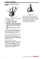
1 – Low Speed - FWD or REV
2 – Low Speed - FWD or REV
3 – NEUTRAL - Power to the propeller
shaft is cut off and the engine idles
4 – Maximum Engine Speed - FWD or
REV
5 – Maximum Engine Speed - FWD or
REV
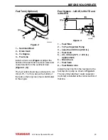
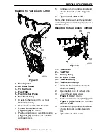
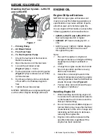
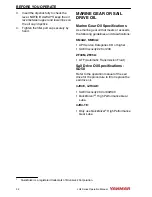
A single handle-type (Figure 22) should be
used to operate the marine gear clutch
(NEUTRAL, FORWARD, and REVERSE)
and to control the engine speed.
The handle controls the direction of the boat
(ahead or astern) and also acts as an
accelerator by increasing engine speed as
the lever is pushed further in FORWARD or
REVERSE directions.
When the handle is pulled out
(Figure 23, (1)), the engine speed can be
controlled without engaging the clutch. The
clutch remains in NEUTRAL, no load
position. Turn the knob (Figure 23, (2))
counterclockwise to move the handle or
clockwise to lock the handle.
(2)
(1)
0004511
Figure 23
Note: Yanmar recommends the use of a
single-lever type for the remote control
system. If only a two-lever type is available
in the market, reduce engine rpm to 1000
rpm or less before engaging and
disengaging the marine gear clutch.
PRODUCT OVERVIEW
26
JH4 Series Operation Manual
Содержание 3JH4E
Страница 1: ...JH4 series OPERATION MANUAL 3JH4E 4JH4AE 4JH4 TE 4JH4 HTE P N 0AJH4 G00102 MARINE ENGINES ...
Страница 18: ...This Page Intentionally Left Blank SAFETY 12 JH4 Series Operation Manual ...
Страница 48: ...This Page Intentionally Left Blank BEFORE YOU OPERATE 42 JH4 Series Operation Manual ...
Страница 56: ...This Page Intentionally Left Blank ENGINE OPERATION 50 JH4 Series Operation Manual ...
Страница 82: ...This Page Intentionally Left Blank PERIODIC MAINTENANCE 76 JH4 Series Operation Manual ...
Страница 101: ...This Page Intentionally Left Blank SPECIFICATIONS JH4 Series Operation Manual 95 ...
Страница 108: ...3JH4E with KM35P KM35A Marine Gear 0004175 Figure 1 SYSTEM DIAGRAMS 102 JH4 Series Operation Manual ...
Страница 109: ...3JH4E with SD50 SD40 Sail Drive 0004176 Figure 2 SYSTEM DIAGRAMS JH4 Series Operation Manual 103 ...
Страница 110: ...4JH4AE with KM35P KM35A2 Marine Gear 0004177 cylinder Figure 3 SYSTEM DIAGRAMS 104 JH4 Series Operation Manual ...
Страница 114: ...4JH4AE with SD50 Sail Drive marked satisfy EN ISO7840 0004590 Figure 7 SYSTEM DIAGRAMS 108 JH4 Series Operation Manual ...
Страница 115: ...4JH4 TE with ZF30M marked satisfy EN ISO7840 0004181 Figure 8 SYSTEM DIAGRAMS JH4 Series Operation Manual 109 ...
Страница 116: ...4JH4 TE with KM4A2 0004182 marked satisfy EN ISO7840 Figure 9 SYSTEM DIAGRAMS 110 JH4 Series Operation Manual ...
Страница 117: ...4JH4 TE with KM4A ZF25A marked satisfy EN ISO7840 0004183 Figure 10 SYSTEM DIAGRAMS JH4 Series Operation Manual 111 ...
Страница 118: ...4JH4 TE with SD50 SD40 marked satisfy EN ISO7840 0004184 Figure 11 SYSTEM DIAGRAMS 112 JH4 Series Operation Manual ...
Страница 119: ...4JH4 HTE with KM4A2 marked satisfy EN ISO7840 0004591 Figure 12 SYSTEM DIAGRAMS JH4 Series Operation Manual 113 ...
Страница 120: ...4JH4 HTE with KMH4A ZF25A marked satisfy EN ISO7840 0004592 Figure 13 SYSTEM DIAGRAMS 114 JH4 Series Operation Manual ...
Страница 121: ...4JH4 HTE with ZF30 0004593 marked satisfy EN ISO7840 Figure 14 SYSTEM DIAGRAMS JH4 Series Operation Manual 115 ...
Страница 134: ...This Page Intentionally Left Blank SYSTEM DIAGRAMS 128 JH4 Series Operation Manual ...
Страница 142: ...136 JH4 Series Operation Manual ...


