CONTROL EQUIPMENT
The equipment in the control room makes remote control operation possible. It consists of
the instrument panel, which is connected to the engine by a wire harness, and the remote
control handle, which is connected by control cables to the engine control lever and marine
gear.
Instrument Panel (Optional)
Equipment and Functions
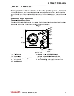
The instrument panel is located in the cockpit. The following instruments enable you to start
or stop the engine and to monitor its condition during operation.
B-Type
0004486
(1)
(2)
(3)
(4)
(5)
(6)
(7)
(8)
(9)
Figure 13
1 – Tachometer
2 – Hourmeter
3 – Moisture Cap for Key Switch
4 – Key Switch
5 – Stop Button
6 – Battery Low Charge Indicator
7 – Water in Sail Drive Seal Indicator
8 – Engine Oil Low Pressure Indicator
9 – Coolant High Temperature Indicator
PRODUCT OVERVIEW
JH4 Series Operation Manual
21
Содержание 3JH4E
Страница 1: ...JH4 series OPERATION MANUAL 3JH4E 4JH4AE 4JH4 TE 4JH4 HTE P N 0AJH4 G00102 MARINE ENGINES ...
Страница 18: ...This Page Intentionally Left Blank SAFETY 12 JH4 Series Operation Manual ...
Страница 48: ...This Page Intentionally Left Blank BEFORE YOU OPERATE 42 JH4 Series Operation Manual ...
Страница 56: ...This Page Intentionally Left Blank ENGINE OPERATION 50 JH4 Series Operation Manual ...
Страница 82: ...This Page Intentionally Left Blank PERIODIC MAINTENANCE 76 JH4 Series Operation Manual ...
Страница 101: ...This Page Intentionally Left Blank SPECIFICATIONS JH4 Series Operation Manual 95 ...
Страница 108: ...3JH4E with KM35P KM35A Marine Gear 0004175 Figure 1 SYSTEM DIAGRAMS 102 JH4 Series Operation Manual ...
Страница 109: ...3JH4E with SD50 SD40 Sail Drive 0004176 Figure 2 SYSTEM DIAGRAMS JH4 Series Operation Manual 103 ...
Страница 110: ...4JH4AE with KM35P KM35A2 Marine Gear 0004177 cylinder Figure 3 SYSTEM DIAGRAMS 104 JH4 Series Operation Manual ...
Страница 114: ...4JH4AE with SD50 Sail Drive marked satisfy EN ISO7840 0004590 Figure 7 SYSTEM DIAGRAMS 108 JH4 Series Operation Manual ...
Страница 115: ...4JH4 TE with ZF30M marked satisfy EN ISO7840 0004181 Figure 8 SYSTEM DIAGRAMS JH4 Series Operation Manual 109 ...
Страница 116: ...4JH4 TE with KM4A2 0004182 marked satisfy EN ISO7840 Figure 9 SYSTEM DIAGRAMS 110 JH4 Series Operation Manual ...
Страница 117: ...4JH4 TE with KM4A ZF25A marked satisfy EN ISO7840 0004183 Figure 10 SYSTEM DIAGRAMS JH4 Series Operation Manual 111 ...
Страница 118: ...4JH4 TE with SD50 SD40 marked satisfy EN ISO7840 0004184 Figure 11 SYSTEM DIAGRAMS 112 JH4 Series Operation Manual ...
Страница 119: ...4JH4 HTE with KM4A2 marked satisfy EN ISO7840 0004591 Figure 12 SYSTEM DIAGRAMS JH4 Series Operation Manual 113 ...
Страница 120: ...4JH4 HTE with KMH4A ZF25A marked satisfy EN ISO7840 0004592 Figure 13 SYSTEM DIAGRAMS 114 JH4 Series Operation Manual ...
Страница 121: ...4JH4 HTE with ZF30 0004593 marked satisfy EN ISO7840 Figure 14 SYSTEM DIAGRAMS JH4 Series Operation Manual 115 ...
Страница 134: ...This Page Intentionally Left Blank SYSTEM DIAGRAMS 128 JH4 Series Operation Manual ...
Страница 142: ...136 JH4 Series Operation Manual ...


