FUEL INJECTION SYSTEM
8-38
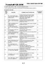
Sensor operation table
42
No normal signals are re-
ceived from the speed sen-
sor.
• Open or short circuit in wire harness.
• Defective speed sensor.
• Malfunction in vehicle speed sensor detect-
ed.
• Malfunction in ECU.
07
44
Error is detected while
reading or writing on EE-
PROM.
• Malfunction in ECU. (The CO adjustment
value is not properly written on or read from
the internal memory.)
60
46
Power supply to the fuel in-
jection system is not nor-
mal.
• Malfunction in the charging system. Refer
to “CHARGING SYSTEM” on page 8-11.
—
50
Faulty ECU memory.
(When this malfunction is
detected in the ECU, the
fault code number might
not appear on the LCD of
the FI diagnostic tool.)
• Malfunction in ECU. (The program and data
are not properly written on or read from the
internal memory.)
—
Fault
code
No.
Symptom
Probable cause of malfunction
Diagnostic
code No.
Diag-
nostic
code
No.
Item
FI diagnostic tool display
Checking method
01
Throttle angle
Check for changes in dis-
played values while open-
ing and closing the throttle.
• Fully closed position
14–20
• Fully open position
97–107
03
Intake air pressure
Displays the intake air pres-
sure.
Set the engine stop switch
to “
”, then operate the
throttle while pushing the
start switch “
”. (If the dis-
play value changes, the
performance is OK.)
05
Intake air temperature
Displays the intake air tem-
perature.
Compare the actually mea-
sured air temperature with
the display value.
06
Coolant temperature
Displays the coolant temper-
ature.
Compare the actually mea-
sured coolant temperature
with the meter display val-
ue.
07
Vehicle speed pulse
0–999
Check that the number in-
creases when the front
wheel is rotated. The num-
ber is cumulative and does
not reset each time the
wheel is stopped.
YamahaR125.COM
Содержание YZF-R125
Страница 1: ...5D7 F8197 E0 YAMAHAR125 COM SERVICE MANUAL YZF R125 ...
Страница 6: ...YamahaR125 COM ...
Страница 8: ...YamahaR125 COM ...
Страница 50: ...LUBRICATION SYSTEM CHART AND DIAGRAMS 2 27 EAS20410 LUBRICATION DIAGRAMS A 1 2 3 4 5 6 7 YamahaR125 COM ...
Страница 52: ...LUBRICATION SYSTEM CHART AND DIAGRAMS 2 29 1 2 3 4 YamahaR125 COM ...
Страница 53: ...LUBRICATION SYSTEM CHART AND DIAGRAMS 2 30 1 Camshaft 2 Crankshaft 3 Main axle 4 Drive axle YamahaR125 COM ...
Страница 54: ...COOLING SYSTEM DIAGRAMS 2 31 EAS20420 COOLING SYSTEM DIAGRAMS 1 2 3 4 5 6 2 4 8 7 2 5 6 9 YamahaR125 COM ...
Страница 60: ...CABLE ROUTING 2 37 A A A B B C C D D E E A C C D E E D B B A 1 1 1 1 1 2 2 2 3 3 3 4 4 4 5 5 YamahaR125 COM ...
Страница 70: ...CABLE ROUTING 2 47 YamahaR125 COM ...
Страница 73: ...YamahaR125 COM ...
Страница 102: ...ELECTRICAL SYSTEM 3 29 YamahaR125 COM ...
Страница 105: ...YamahaR125 COM ...
Страница 172: ...CHAIN DRIVE 4 67 YamahaR125 COM ...
Страница 181: ...ENGINE REMOVAL 5 6 2 2 4 1 3 YamahaR125 COM ...
Страница 263: ...THROTTLE BODY 7 8 YamahaR125 COM ...
Страница 264: ...AIR INDUCTION SYSTEM 7 9 EAS27040 AIR INDUCTION SYSTEM 1 2 3 YamahaR125 COM ...
Страница 268: ...AIR INDUCTION SYSTEM 7 13 YamahaR125 COM ...
Страница 271: ...YamahaR125 COM ...
Страница 283: ...CHARGING SYSTEM 8 12 1 AC magneto 3 Rectifier regulator 4 Main fuse 9 Battery YamahaR125 COM ...
Страница 285: ...CHARGING SYSTEM 8 14 YamahaR125 COM ...
Страница 295: ...SIGNALING SYSTEM 8 24 YamahaR125 COM ...
Страница 299: ...COOLING SYSTEM 8 28 YamahaR125 COM ...
Страница 323: ...FUEL INJECTION SYSTEM 8 52 YamahaR125 COM ...
Страница 327: ...FUEL PUMP SYSTEM 8 56 YamahaR125 COM ...
Страница 353: ...YamahaR125 COM ...
Страница 354: ...YamahaR125 COM ...


