FUEL INJECTION SYSTEM
8-33
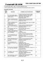
Self-Diagnostic Function table
Fault
code No.
Item
Symptom
Able / un-
able to start
Able / un-
able to
drive
12
Crankshaft position
sensor
No normal signals are received
from the crankshaft position sen-
sor.
Unable
Unable
13
Intake air pressure
sensor
(open or short circuit)
Intake air pressure sensor: open
or short circuit detected.
Able
Able
14
Intake air pressure
sensor
(system)
Intake air pressure sensor: system
malfunction (clogged hole).
Able
Able
15
Throttle position sen-
sor
(open or short circuit)
Throttle position sensor: open or
short circuit detected.
Able
Able
16
Throttle position sen-
sor
(stuck)
Throttle position sensor is stuck
Able
Able
19
Blue/yellow ECU lead
(broken or discon-
nected)
A break or disconnection of the
blue/yellow lead of the ECU is de-
tected.
Unable
Unable
21
Coolant temperature
sensor
Coolant temperature sensor: open
or short circuit detected.
Able
Able
22
Intake air tempera-
ture sensor
(open or short circuit)
Intake air temperature sensor:
open or short circuit detected.
Able
Able
30
Lean angle sensor
(latch up detected)
No normal signal is received from
the lean angle sensor.
Unable
Unable
33
Ignition coil
(open circuit)
Primary lead of the ignition coil:
open circuit detected.
Unable
Unable
39
Fuel injector
Fuel injector: open or short circuit
detected.
Unable
Unable
41
Lean angle sensor
(open or short circuit)
Lean angle sensor: open or short
circuit detected.
Unable
Unable
42
Speed sensor
No normal signals are received
from the speed sensor.
Able
Able
44
EEPROM
Error is detected while reading
from or writing on EEPROM.
Able
Able
46
Vehicle system power
supply
(Monitoring voltage)
Malfunction in the charging sys-
tem.
Able
Able
50
ECU internal malfunc-
tion
(memory check error)
Faulty ECU memory. (When this
malfunction is detected in the
ECU, the fault code number might
not appear on the meter.)
Unable
Unable
—
Start unable warning
Engine trouble warning light flash-
es when the start switch is turned
ON.
Unable
Unable
YamahaR125.COM
Содержание YZF-R125
Страница 1: ...5D7 F8197 E0 YAMAHAR125 COM SERVICE MANUAL YZF R125 ...
Страница 6: ...YamahaR125 COM ...
Страница 8: ...YamahaR125 COM ...
Страница 50: ...LUBRICATION SYSTEM CHART AND DIAGRAMS 2 27 EAS20410 LUBRICATION DIAGRAMS A 1 2 3 4 5 6 7 YamahaR125 COM ...
Страница 52: ...LUBRICATION SYSTEM CHART AND DIAGRAMS 2 29 1 2 3 4 YamahaR125 COM ...
Страница 53: ...LUBRICATION SYSTEM CHART AND DIAGRAMS 2 30 1 Camshaft 2 Crankshaft 3 Main axle 4 Drive axle YamahaR125 COM ...
Страница 54: ...COOLING SYSTEM DIAGRAMS 2 31 EAS20420 COOLING SYSTEM DIAGRAMS 1 2 3 4 5 6 2 4 8 7 2 5 6 9 YamahaR125 COM ...
Страница 60: ...CABLE ROUTING 2 37 A A A B B C C D D E E A C C D E E D B B A 1 1 1 1 1 2 2 2 3 3 3 4 4 4 5 5 YamahaR125 COM ...
Страница 70: ...CABLE ROUTING 2 47 YamahaR125 COM ...
Страница 73: ...YamahaR125 COM ...
Страница 102: ...ELECTRICAL SYSTEM 3 29 YamahaR125 COM ...
Страница 105: ...YamahaR125 COM ...
Страница 172: ...CHAIN DRIVE 4 67 YamahaR125 COM ...
Страница 181: ...ENGINE REMOVAL 5 6 2 2 4 1 3 YamahaR125 COM ...
Страница 263: ...THROTTLE BODY 7 8 YamahaR125 COM ...
Страница 264: ...AIR INDUCTION SYSTEM 7 9 EAS27040 AIR INDUCTION SYSTEM 1 2 3 YamahaR125 COM ...
Страница 268: ...AIR INDUCTION SYSTEM 7 13 YamahaR125 COM ...
Страница 271: ...YamahaR125 COM ...
Страница 283: ...CHARGING SYSTEM 8 12 1 AC magneto 3 Rectifier regulator 4 Main fuse 9 Battery YamahaR125 COM ...
Страница 285: ...CHARGING SYSTEM 8 14 YamahaR125 COM ...
Страница 295: ...SIGNALING SYSTEM 8 24 YamahaR125 COM ...
Страница 299: ...COOLING SYSTEM 8 28 YamahaR125 COM ...
Страница 323: ...FUEL INJECTION SYSTEM 8 52 YamahaR125 COM ...
Страница 327: ...FUEL PUMP SYSTEM 8 56 YamahaR125 COM ...
Страница 353: ...YamahaR125 COM ...
Страница 354: ...YamahaR125 COM ...


