3-22
CHASSIS
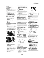
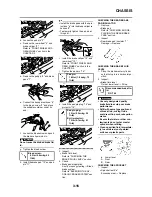
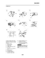
• The handlebar upper holder should
be installed with the punched mark
"a" forward.
• Install the handlebar so that the
marks "b" are in place on both
sides.
• Install the handlebar so that the pro-
jection "c" of the handlebar upper
holder is positioned at the mark on
the handlebar as shown.
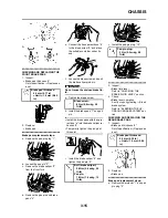
• Insert the end of the fuel breather
hose "12" into the hole in the steer-
ing stem.
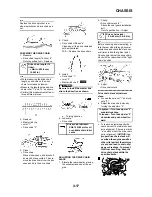
First tighten the bolts on the front
side of the handlebar upper holder,
and then tighten the bolts on the
rear side.
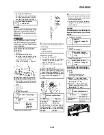
Steering stem nut:
145 Nm (14.5 m•kg, 105
ft•lb)
Handlebar upper holder:
28 Nm (2.8 m•kg, 20
ft•lb)
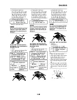
Pinch bolt (upper brack-
et):
21 Nm (2.1 m•kg, 15
ft•lb)
Number plate:
7 Nm (0.7 m•kg, 5.1
ft•lb)
Содержание YZ250F(Y)
Страница 4: ......
Страница 39: ...2 17 LUBRICATION DIAGRAMS 1 Crankshaft 2 Oil filter element 3 Oil tank 4 Oil hose A From oil pump...
Страница 59: ...3 13 ENGINE INTAKE EXHAUST...
Страница 189: ......
Страница 190: ...PRINTED IN JAPAN E PRINTED ON RECYCLED PAPER YAMAHA MOTOR CO LTD 2500 SHINGAI IWATA SHIZUOKA JAPAN...


