background image

3-19

CHASSIS

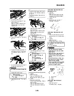
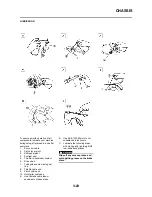
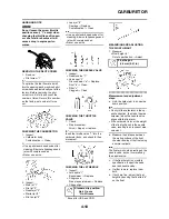
• STANDARD POSITION:

This is the position which is back 
by the specific number of clicks 
from the fully turned-in position.

Do not force the adjuster past the 
minimum or maximum extent of 
adjustment. The adjuster may be 
damaged.

Always adjust each front fork to 
the same setting. Uneven adjust-
ment can cause poor handling and 
loss of stability.

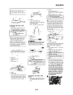
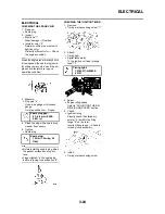
CHECKING THE REAR SHOCK 
ABSORBER

1. Inspect:

• Swingarm smooth action

Abnormal noise/unsmooth action

Grease the pivoting points or 

repair the pivoting points.
Damage/oil leakage

Replace.

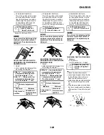
ADJUSTING THE REAR SHOCK 
ABSORBER SPRING PRELOAD

1. Elevate the rear wheel by placing 

the suitable stand under the en-
gine.

2. Remove:

• Rear frame

3. Measure:

• Spring fitting length

The I.D. mark "a" is marked at the end 
of the spring.

4. Adjust:

• Spring preload

Adjustment steps:

a. Loosen the locknut "1".
b. Loosen the adjuster "2" until there 

is some clearance between the 
spring and adjuster.

c. Measure the spring free length 

"a".

d. Turn the adjuster "2".

• Be sure to remove all dirt and mud 

from around the locknut and adjust-
er before adjustment.

• The length of the spring (installed) 

changes 1.5 mm (0.06 in) per turn 
of the adjuster.

Never attempt to turn the adjuster 
beyond the maximum or minimum 
setting.

e. Tighten the locknut.

5. Install:

• Rear frame (upper)

• Rear frame (lower)

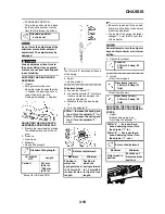
ADJUSTING THE REAR SHOCK 
ABSORBER REBOUND DAMPING 
FORCE

1. Adjust:

• Rebound damping force

By turning the adjuster "1".

Standard position:

9 clicks out

Standard fitting length:

I.D. MARK/ 

Q'TY

Length

Yellow/1

251 mm
(9.98 in)
* 248 mm
(9.76 in)

* Except for USA and CDN

Stiffer 

Increase the spring pre-

load. (Turn the adjuster "2" in.)

Softer

Decrease the spring pre-

load. (Turn the adjuster "2" 
out.)

Extent of adjustment:

Maximum

Minimum

Position in 
which the 
spring is turned 
in 13 mm (0.51 
in) from its free 
length.

Position in 
which the 
spring is turned 
in 1.5 mm (0.06 
in) from its free 
length.

Locknut:

30 Nm (3.0 m•kg, 22 
ft•lb)

Rear frame (upper):

38 Nm (3.8 m•kg, 27 
ft•lb)

Rear frame (lower):

32 Nm (3.2 m•kg, 23 
ft•lb)

Stiffer "a" 

Increase the re-

bound damping force. (Turn 
the adjuster "1" in.)

Softer "b" 

Decrease the re-

bound damping force. (Turn 
the adjuster "1" out.)

Extent of adjustment:

Maximum

Minimum

Fully turned in 
position

20 clicks out 
(from maximum 
position)

Содержание YZ250F(Y)

Страница 1: ...ce manuel avant la premi re utilisation du v hicule Read this manual carefully before operating this vehicle Bitte lesen Sie diese Bedienungsanleitung sorgf ltig durch bevor Sie das Fahrzeug in Betri...

Страница 2: ...le Le manuel doit tre remis avec le v hicule en cas de vente de ce dernier Bitte lesen Sie diese Bedienungsanleitung sorgf ltig durch bevor Sie das Fahrzeug in Betrieb nehmen Diese Bedienungsanleitung...

Страница 3: ...Z250F Y 2009 2009 5XC 28199 35 E0 5XC 28199 35 E0 OWNER S SERVICE MANUAL OWNER S SERVICE MANUAL Read this manual carefully before operating this vehicle Read this manual carefully before operating thi...

Страница 4: ......

Страница 5: ...S SERVICE MANUAL 2008 by Yamaha Motor Co Ltd 1st Edition May 2008 All rights reserved Any reprinting or unauthorized use without the written permission of Yamaha Motor Co Ltd is expressly prohibited P...

Страница 6: ...acter istics THIS MACHINE IS DESIGNED TO BE RIDDEN BY THE OPERATOR ONLY Do not carry passengers on this machine ALWAYS WEAR PROTECTIVE APPAREL When operating this machine al ways wear an approved helm...

Страница 7: ...n to find the required fore edge symbol mark and go to a page for required item and de scription MANUAL FORMAT All of the procedures in this manual are organized in a sequential step by step format Th...

Страница 8: ...informa tion the step by step format sup plements 5 are given in addition to the exploded diagram and job instruction chart ILLUSTRATED SYMBOLS Refer to the illustration Illustrated symbols 1 to 7 are...

Страница 9: ...TABLE OF CONTENTS GENERAL INFORMATION 1 SPECIFICATIONS 2 REGULAR INSPECTION AND ADJUSTMENTS 3 ENGINE 4 CHASSIS 5 ELECTRICAL 6 TUNING 7...

Страница 10: ...3 14 ELECTRICAL 3 24 CHAPTER 4 ENGINE SEAT FUEL TANK AND SIDE COVERS 4 1 EXHAUST PIPE AND SILENCER 4 3 RADIATOR 4 5 CARBURETOR 4 7 CAMSHAFTS 4 14 CYLINDER HEAD 4 19 VALVES AND VALVE SPRINGS 4 21 CYLIN...

Страница 11: ...t to change without notice 1 Clutch lever 2 Hot starter lever 3 Front brake lever 4 Throttle grip 5 Radiator cap 6 Fuel tank cap 7 Engine stop switch 8 Kickstarter crank 9 Fuel tank 10 Radiator 11 Coo...

Страница 12: ...joint 1 prevents fuel from flowing out and is installed to the fuel tank breather hose In this installation make sure the arrow faces the fuel tank and also downward SPARK PLUG WRENCH This spark plug...

Страница 13: ...mped letters must be on the side exposed to view When in stalling oil seal s apply a light coating of lightweight lithium base grease to the seal lip s Oil the bearings liberally when installing Do no...

Страница 14: ...se separating tool YU 1135 A 90890 01135 These tool is used to remove the crankshaft from either case Flywheel puller YM 1189 90890 01189 This tool is used to remove the fly wheel magneto Rotor holdin...

Страница 15: ...1500 90890 01500 This tool is used to loosen or tighten the base valve Cap bolt ring wrench YM 01501 90890 01501 This tool is used to loosen or tighten the damper assembly Fork seal driver YM A0948 90...

Страница 16: ...ss securing nut Valve guide remover Intake 4 0 mm 0 16 in Exhaust 4 5 mm 0 18 in YM 4111 90890 04111 YM 4116 90890 04116 This tool is needed to remove and install the valve guide Valve guide installer...

Страница 17: ...ecessary for checking the ignition system compo nents Digital tachometer YU 39951 B 90890 06760 This tool is needed for observing en gine rpm YAMAHA Bond No 1215 ThreeB ond No 1215 90890 85505 This se...

Страница 18: ...AR BRAKE PEDAL The rear brake pedal 1 is located on the right side of the machine Press down on the brake pedal to activate the rear brake FUEL COCK The fuel cock supplies fuel from the tank to carbur...

Страница 19: ...e cold starter knob to its original position and run the en gine at 3 000 5 000 r min for 1 or 2 minutes Since this model is equipped with an accelerator pump if the engine is raced the throttle opene...

Страница 20: ...2 open low to me dium speed for about one hour 6 Restart the engine and check the operation of the machine through out its entire operating range Re start the machine and operate it for about 10 to 15...

Страница 21: ...nk type Assembly of links Link to frame Link to rear shock absorber Link to swingarm Installation of rear shock absorber Rear shock absorber to frame Installation of swingarm Tightening of pivot shaft...

Страница 22: ...in with a paper towel and lubri cate the chain to prevent rust 7 Clean the seat with a vinyl uphol stery cleaner to keep the cover pliable and glossy 8 Automotive wax may be applied to all painted or...

Страница 23: ...Without oil and fuel 92 7 kg 204 lb Engine Engine type Liquid cooled 4 stroke DOHC Cylinder arrangement Single cylinder forward inclined Displacement 249 cm3 8 76 Imp oz 8 42 US oz Bore stroke 77 0 5...

Страница 24: ...ystem Chain drive Secondary reduction ratio 49 13 3 769 51 13 3 923 Transmission type Constant mesh 5 speed Operation Left foot operation Gear ratio 1st 30 14 2 143 2nd 28 16 1 750 3rd 29 20 1 450 4th...

Страница 25: ...2 in Cylinder Bore size 77 00 77 01 mm 3 0315 3 0319 in Out of round limit 0 05 mm 0 002 in Camshaft Drive method Chain drive Left Camshaft cap inside diameter 22 000 22 021 mm 0 8661 0 8670 in Camsha...

Страница 26: ...0 0059 in EX 0 17 0 22 mm 0 0067 0 0087 in Valve dimensions A head diameter IN 22 9 23 1 mm 0 9016 0 9094 in A head diameter EX 24 4 24 6 mm 0 9606 0 9685 in B face width IN 2 26 mm 0 089 in B face w...

Страница 27: ...4 in Valve seat width IN 0 9 1 1 mm 0 0354 0 0433 in 1 6 mm 0 0630 in Valve seat width EX 0 9 1 1 mm 0 0354 0 0433 in 1 6 mm 0 0630 in Valve spring Free length IN 37 81 mm 1 49 in 36 81mm 1 45 in Free...

Страница 28: ...B T 0 90 2 75 mm 0 04 0 11 in End gap installed 0 15 0 25 mm 0 006 0 010 in 0 50mm 0 020 in Side clearance installed 0 030 0 065 mm 0 0012 0 0026 in 0 12 mm 0 005 in 2nd ring Type Taper Dimensions B...

Страница 29: ...44 mm 0 0004 0 0017 in Clutch release method Inner push cam push Shifter Shifter type Cam drum and guide bar Guide bar bending limit 0 05 mm 0 002 in Kickstarter Type Kick and ratchet type Carburetor...

Страница 30: ...or capacity total 0 58 L 0 51 Imp qt 0 61 US qt Water pump Type Single suction centrifugal pump Item Standard Limit Item Standard Limit Steering system Steering bearing type Taper roller bearing Front...

Страница 31: ...k 50 60 mm 2 0 2 4 in Chain length 15 links 242 9 mm 9 563 in Front disc brake Disc outside dia Thickness 250 3 0 mm 9 84 0 12 in 250 2 5 mm 9 84 0 10 in Pad thickness 4 4 mm 0 17 in 1 0 mm 0 04 in Ma...

Страница 32: ...mm 0 24 in Primary coil resistance 0 08 0 10 at 20 C 68 F Secondary coil resistance 4 6 6 8 k at 20 C 68 F Part to be tightened Thread size Q ty Tightening torque Nm m kg ft lb Spark plug M10S 1 0 1...

Страница 33: ...0 1 2 0 2 1 4 Hot starter cable adjust bolt and locknut M6 0 75 1 4 0 4 2 9 Air filter case M6 1 0 2 8 0 8 5 8 Air filter joint and air filter case M5 0 8 1 4 0 4 2 9 Air filter element M6 1 0 1 2 0...

Страница 34: ...steering ring nut M28 1 0 1 Refer to TIP Front fork and damper assembly M51 1 5 2 30 3 0 22 Front fork and adjuster M22 1 25 2 55 5 5 40 Damper assembly and base valve M42 1 5 2 29 2 9 21 Adjuster and...

Страница 35: ...gine bracket and frame M8 1 25 4 38 3 8 27 Engine and engine bracket upper M10 1 25 1 55 5 5 40 Lower engine guard M6 1 0 3 10 1 0 7 2 Right engine guard M6 1 0 1 10 1 0 7 2 CDI unit bracket M6 1 0 2...

Страница 36: ...0 4 7 0 7 5 1 Air scoop and fuel tank M6 1 0 6 7 0 7 5 1 Air scoop and radiator guard lower M6 1 0 2 7 0 7 5 1 Front fender M6 1 0 4 7 0 7 5 1 Rear fender front M6 1 0 2 7 0 7 5 1 Rear fender rear M6...

Страница 37: ...s should be at room temperature A Distance between flats B Outside thread diameter DEFINITION OF UNITS A Nut B Bolt TORQUE SPECIFI CATION Nm m kg ft lb 10 mm 6 mm 6 0 6 4 3 12 mm 8 mm 15 1 5 11 14 mm...

Страница 38: ...2 16 LUBRICATION DIAGRAMS LUBRICATION DIAGRAMS 1 Oil filter element 2 Oil pump 3 Drive axle 4 Main axle 5 Intake camshaft 6 Exhaust camshaft 7 Oil tank 8 Oil delivery pipe A To oil tank...

Страница 39: ...2 17 LUBRICATION DIAGRAMS 1 Crankshaft 2 Oil filter element 3 Oil tank 4 Oil hose A From oil pump...

Страница 40: ...el hose 12 Carburetor overflow hose A Insert the end of the fuel tank breather hose into the hole in the steering stem B Install the connector cover so that it does not come in between the radiator ho...

Страница 41: ...the fuel hose on the out side of throttle position sensor lead H Pass the carburetor breater hos es so that they are not pinched between the upper engine bracket and carburetor I Pass the carburetor...

Страница 42: ...ine stop switch lead 14 Sub wire harness 15 CDI unit bracket 16 CDI unit 17 Throttle cable 18 Cylinder head breather hose 19 Hot starter cable protector 20 Rubber cap A Fasten the hot starter cable th...

Страница 43: ...t at the white taped portion of the subwire har ness and with the clamp ends facing downward H Locate the clamp ends in the ar rowed range I Fasten the neutral switch lead and CDI magneto lead over th...

Страница 44: ...Cylinder head breather hose 6 Clamp 7 Rear arm bracket A Pass the throttle cables over the radiator hose 2 B Pass the cylinder head breather hose so that it does not contact the ignition coil C Fasten...

Страница 45: ...directs as shown and lightly touches the projec tion on the brake caliper B Pass the brake hose into the brake hose holders C If the brake hose contacts the spring rear shock absorber correct its twis...

Страница 46: ...hose 8 Hose guide A Fasten the engine stop switch lead to the handlebar B Pass the clutch cable and hot starter cable through the cable guide C Pass the brake hose in front of the number plate D Pass...

Страница 47: ...NGINE OIL Replace Inspect OIL FILTER ELEMENT OIL STRAINER Clean VALVES Check the valve clearances The engine must be cold Inspect Check the valve seats and valve stems for wear Replace VALVE SPRINGS I...

Страница 48: ...spect and clean CARBURETOR Inspect adjust and clean SPARK PLUG Inspect and clean Replace DRIVE CHAIN Use chain lube Lubricate slack alignment Chain slack 50 60 mm 2 0 2 4 in Replace COOLING SYSTEM Che...

Страница 49: ...FRONT FORKS Inspect and adjust Replace oil Suspension oil S1 Replace oil seal FRONT FORK OIL SEAL AND DUST SEAL Clean and lube Lithium base grease PROTECTOR GUIDE Replace REAR SHOCK ABSORBER Inspect a...

Страница 50: ...et bolt Inspect bearings Replace bearings Lubricate Lithium base grease THROTTLE CONTROL CABLE Check routing and connection Lubricate Yamaha cable lube or SAE 10W 30 motor oil Inspect and clean thrott...

Страница 51: ...lack and alignment Check that the drive chain is lubricated properly P 3 17 18 Wheels Check for excessive wear and tire pressure Check for loose spokes and have no excessive play P 3 20 21 Steering Ch...

Страница 52: ...clean tap water 5 Install Copper washer Coolant drain bolt 6 Fill Radiator Engine To specified level Do not mix more than one type of ethylene glycol antifreeze con taining corrosion inhibitors for al...

Страница 53: ...UTCH CABLE FREE PLAY 1 Check Clutch lever free play a Out of specification Adjust 2 Adjust Clutch lever free play Clutch lever free play adjustment steps a Loosen the locknuts 1 b Turn the adjuster 2...

Страница 54: ...oper ation of hot starter CLEANING THE AIR FILTER ELEMENT Proper air filter maintenance is the biggest key to preventing premature engine wear and damage Never run the engine without the air filter e...

Страница 55: ...arm up for several minutes 6 Turn off the engine and inspect the oil level once again Wait a few minutes until the oil settles before inspecting the oil level CHANGING THE ENGINE OIL 1 Start the engin...

Страница 56: ...the fuel flow at a smaller throttle opening each machine s pilot screw has been individually set at the factory Before adjusting the pilot screw turn it in fully and count the number of turns Record...

Страница 57: ...ve clearance Out of specification Adjust Checking steps a Turn the crankshaft counterclock wise with a wrench b Align the T D C mark a on the rotor with the align mark b on the crankcase cover when pi...

Страница 58: ...d number to use Use the new pad number only as a guide when verifying the valve clear ance adjustment f Install the new pads 3 and the valve lifters 4 Apply the engine oil on the valve lift ers Apply...

Страница 59: ...3 13 ENGINE INTAKE EXHAUST...

Страница 60: ...bleeding procedure when the tiny bubbles in the system have disap peared j Add brake fluid to the level line on the reservoir Check the operation of the brake after bleeding the brake system 3 Install...

Страница 61: ...the brake caliper re cesses b Temporarily tighten the pad pin at this point i Install the brake caliper 8 and tighten the pad pin 9 j Install the pad pin plug 10 3 Inspect Brake fluid level Refer to C...

Страница 62: ...ion A softy or spongy feeling Bleed brake system Refer to BLEEDING THE HY DRAULIC BRAKE SYSTEM sec tion CHECKING THE REAR BRAKE PAD INSULATOR 1 Remove Brake pad Refer to CHECKING AND RE PLACING THE RE...

Страница 63: ...the en gine 2 Check Drive chain slack a Above the seal guard installation bolt Out of specification Adjust Before checking and or adjusting ro tate the rear wheel through several revolutions and check...

Страница 64: ...E FRONT FORK REBOUND DAMPING FORCE 1 Adjust Rebound damping force By turning the adjuster 1 STANDARD POSITION This is the position which is back by the specific number of clicks from the fully turned...

Страница 65: ...mud from around the locknut and adjust er before adjustment The length of the spring installed changes 1 5 mm 0 06 in per turn of the adjuster Never attempt to turn the adjuster beyond the maximum or...

Страница 66: ...er with the punch mark b on the adjuster body Do not force the adjuster past the minimum or maximum extent of adjustment The adjuster may be damaged CHECKING THE TIRE PRESSURE 1 Measure Tire pressure...

Страница 67: ...h action Adjust steer ing ring nut 4 Adjust Steering ring nut Steering ring nut adjustment steps a Remove the number plate b Remove the handlebar and upper bracket c Loosen the steering ring nut 1 usi...

Страница 68: ...older is positioned at the mark on the handlebar as shown Insert the end of the fuel breather hose 12 into the hole in the steer ing stem First tighten the bolts on the front side of the handlebar upp...

Страница 69: ...ot 5 Throttle to handlebar contact 6 Drive chain 7 Tube guide cable winding por tion 8 Throttle cable end 9 Clutch cable end 10 Hot starter cable end A Use Yamaha cable lube or equivalent on these are...

Страница 70: ...r if necessary 5 Tighten Spark plug Before installing a spark plug clean the gasket surface and plug sur face Finger tighten a the spark plug before torquing to specification b CHECKING THE IGNITION T...

Страница 71: ...nspection adjustment disassembly or reassembly only by reference to this manual It may lead to servicing trouble and mechanical damage SEAT FUEL TANK AND SIDE COVERS REMOVING THE SEAT FUEL TANK AND SI...

Страница 72: ...a is inserted into the band of the number plate Pull the band off the projection before removal Remove the hot starter cable 2 and clutch cable 3 from the cable guide b on the number plate The projec...

Страница 73: ...t name Q ty Remarks A Except for USA and CDN Right side cover Refer to SEAT FUEL TANK AND SIDE COVERS section 1 Bolt silencer clamp 1 Only loosening 2 Bolt silencer front 1 3 Bolt silencer rear 1 4 Co...

Страница 74: ...e care not to allow the fiber out of place when installing the inner pipe INSTALLING THE SILENCER AND EXHAUST PIPE 1 Install Gasket Exhaust pipe 1 Nut exhaust pipe 2 First temporarily install both nut...

Страница 75: ...NT sec tion in the CHAPTER 3 Seat and fuel tank Refer to SEAT FUEL TANK AND SIDE COVERS section 1 Radiator guard 2 2 Radiator hose clamp 8 Only loosening 3 Radiator hose 1 1 4 Left radiator 1 5 Radiat...

Страница 76: ...n Repair replace INSTALLING THE RADIATOR 1 Install O ring 1 Radiator pipe 1 2 Bolt radiator pipe 3 Apply the lithium soap base grease on the O ring 2 Install Radiator breather hose 1 Radiator hose 2 2...

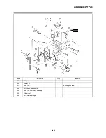
Страница 77: ...le position sensor lead coupler 1 3 Throttle cable cover 1 4 Throttle cable 2 5 Clamp air filter joint 1 Loosen the screw air filter joint 6 Clamp carburetor joint 1 Loosen the screws carburetor joint...

Страница 78: ...sing cover 1 3 Screw throttle shaft 1 4 Throttle valve 1 5 Needle holder 1 6 Jet needle 1 7 Accelerator pump cover 1 8 Spring 1 9 Diaphragm accelerator pump 1 10 Float chamber 1 11 Leak jet 1 12 Pilot...

Страница 79: ...URETOR 19 Pilot jet 1 20 Starter jet 1 21 Push rod 1 Pull the push rod 22 Throttle shaft assembly 1 23 Push rod link lever assembly 1 24 Pilot air jet 1 25 Cold starter plunger 1 Order Part name Q ty...

Страница 80: ...logged Clean CHECKING THE THROTTLE VALVE 1 Check Free movement Stick Repair or replace Insert the throttle valve 1 into the carburetor body and check for free movement CHECKING THE JET NEEDLE 1 Inspec...

Страница 81: ...fits on the stopper a of the lever 2 4 Install Spring 2 1 To lever 2 2 5 Install Push rod link lever assembly 1 Make sure the stopper a of the spring 2 fits into the recess b in the carburetor 6 Inst...

Страница 82: ...of turns recorded before removing 13 Install O ring Leak jet 1 Float chamber 2 Bolt float chamber 3 Cable holder throttle stop screw cable 4 Hose holder carburetor breather hose 5 14 Install Diaphragm...

Страница 83: ...oint 1 2 Install Carburetor 1 Install the projection a between the carburetor joint slots 3 Install Hot starter plunger 1 4 Tighten Bolt carburetor joint 1 Bolt air filter joint 2 5 Install Throttle c...

Страница 84: ...Order Part name Q ty Remarks Seat and fuel tank Refer to SEAT FUEL TANK AND SIDE COVERS section 1 Spark plug 1 2 Cylinder head breather hose 1 3 Bolt cylinder head cover 2 4 Cylinder head cover 1 5 Cy...

Страница 85: ...haft end accessing screw 1 Refer to removal section 3 Timing chain tensioner cap bolt 1 Refer to removal section 4 Timing chain tensioner 1 Refer to removal section 5 Camshaft cap 2 Refer to removal s...

Страница 86: ...ap 2 Clip Remove the bolts camshaft cap in a crisscross pattern working from the outside in The bolts camshaft cap must be removed evenly to prevent dam age to the cylinder head cam shafts or camshaft...

Страница 87: ...decompression mechanism cam lever pin 2 projects from the camshaft CHECKING THE TIMING CHAIN TENSIONER 1 Check While pressing the tensioner rod lightly with fingers use a thin screwdriver 1 and wind...

Страница 88: ...se a thin screwdriver and wind the tension er rod up fully clockwise b With the rod fully wound and the chain tensioner UP mark a fac ing upward install the gasket 1 and the timing chain tensioner 2 a...

Страница 89: ...cer Refer to EXHAUST PIPE AND SILENCER section Radiator hose 1 Disconnect at cylinder head side Carburetor Refer to CARBURETOR section Camshaft Refer to CAMSHAFTS section Upper engine bracket Refer to...

Страница 90: ...several times INSTALLING THE CYLINDER HEAD 1 Install Dowel pin 1 Cylinder head gasket 2 Timing chain guide exhaust side 3 Cylinder head 4 While pulling up the timing chain in stall the timing chain g...

Страница 91: ...e Q ty Remarks Cylinder head Refer to CYLINDER HEAD section 1 Valve lifter 5 Refer to removal section 2 Adjusting pad 5 Refer to removal section 3 Valve cotter 10 Refer to removal section 4 Valve spri...

Страница 92: ...to 100 C 212 F a Remove the valve guide using a valve guide remover 1 b Install the new valve guide using a valve guide remover 1 and valve guide installer 2 c After installing the valve guide bore t...

Страница 93: ...mpound enter the gap between the valve stem and the guide b Apply molybdenum disulfide oil to the valve stem c Install the valve into the cylinder head d Turn the valve until the valve face and valve...

Страница 94: ...ger pitch d facing upward e Smaller pitch 3 Install Valve cotter While compressing the valve spring with a valve spring compressor 1 in stall the valve cotters 4 To secure the valve cotters onto the v...

Страница 95: ...TON Order Part name Q ty Remarks Cylinder head Refer to CYLINDER HEAD section 1 Bolt cylinder 1 2 Cylinder 1 3 Piston pin clip 2 Refer to removal section 4 Piston pin 1 Refer to removal section 5 Pist...

Страница 96: ...e piston bottom edge d If out of specification replace the piston and piston rings as a set e Calculate the piston to cylinder clearance with following formula f If out of specification replace the cy...

Страница 97: ...ng Offset the piston ring end gaps as shown a Top ring end b 2nd ring end c Oil ring end upper d Oil ring e Oil ring end lower 3 Install Piston 1 Piston pin 2 Piston pin clip 3 Apply engine oil onto t...

Страница 98: ...he cylinder with one hand while compressing the piston rings with the other hand Pass the timing chain 3 through the timing chain cavity Be careful not to damage the tim ing chain guide 4 during insta...

Страница 99: ...ER 3 Brake pedal Refer to ENGINE REMOVAL section Clutch cable Disconnect at engine side 1 Clutch cover 1 2 Clutch spring 5 3 Pressure plate 1 4 Push rod 1 1 5 Circlip 1 6 Washer 1 7 Bearing 1 8 Ball 1...

Страница 100: ...4 30 CLUTCH 14 Clutch boss 1 Refer to removal section 15 Thrust washer 1 16 Primary driven gear 1 17 Spacer 1 18 Washer 1 19 Push lever shaft 1 Order Part name Q ty Remarks...

Страница 101: ...1 Measure Clutch plate warpage Out of specification Replace clutch plate as a set Use a surface plate 1 and thick ness gauge 2 CHECKING THE PUSH LEVER SHAFT 1 Inspect Push lever shaft 1 Wear damage Re...

Страница 102: ...ction plates and clutch plates 5 Install Bearing 1 Washer 2 Circlip 3 To push rod 1 4 Apply the engine oil on the bearing and washer 6 Install Push rod 2 1 Ball 2 Push rod 1 3 Apply the engine oil on...

Страница 103: ...the coolant Refer to CHANGING THE COOLANT sec tion in the CHAPTER 3 Radiator hose 3 Disconnect at water pump side Exhaust pipe Refer to EXHAUST PIPE AND SILENCER section Brake pedal Refer to ENGINE RE...

Страница 104: ...ER ELEMENT AND WATER PUMP 9 Washer 1 Refer to removal section 10 Impeller shaft 1 Refer to removal section 11 Oil seal 2 Refer to removal section 12 Bearing 1 Refer to removal section Order Part name...

Страница 105: ...damage Replace CHECKING THE BEARING 1 Inspect Bearing Rotate inner race with a finger Rough spot seizure Replace CHECKING THE OIL SEAL 1 Inspect Oil seal 1 Wear damage Replace INSTALLING THE OIL SEAL...

Страница 106: ...t the crankcase cover when it is pulled 2 Install Oil hose 1 Bolt oil hose 2 3 Install Copper washer 1 Oil delivery pipe 2 Union bolt M8 3 Union bolt M10 4 INSTALLING THE WATER PUMP HOUSING 1 Install...

Страница 107: ...IL FILTER ELEMENT AND WA TER PUMP section Stator Refer to CDI MAGNETO section 1 Nut primary drive gear 1 Refer to removal section 2 Nut balancer shaft driven gear 1 Refer to removal section 3 Lock was...

Страница 108: ...the center a of the balancer shaft weight along the line connect ing the centers of the crankshaft and balancer shaft 2 Install Balancer shaft driven gear 1 Install the balancer shaft driven gear ont...

Страница 109: ...ankcase cover Refer to OIL FILTER ELEMENT AND WA TER PUMP section 1 Circlip 1 2 Washer 1 3 Oil pump drive gear 1 4 Oil pump assembly 1 5 Outer rotor 2 1 6 Circlip 1 7 Inner rotor 2 1 8 Dowel pin 1 9 O...

Страница 110: ...THE OIL TANK Order Part name Q ty Remarks Drain the engine oil Refer to CHANGING THE ENGINE OIL section in the CHAPTER 3 1 Oil hose 2 1 2 Oil hose 1 1 3 Dowel pin 2 4 Oil tank breather hose 1 5 Oil t...

Страница 111: ...tor 1 1 Apply the engine oil on the outer rotor 1 3 Install Oil pump cover 1 Screw oil pump cover 2 Dowel pin 3 Inner rotor 2 4 Circlip 5 Apply the engine oil on the inner ro tor 2 Fit the dowel pin i...

Страница 112: ...ection 1 Kick idle gear 1 2 Kick shaft assembly 1 Refer to removal section 3 Spring guide 1 4 Torsion spring 1 5 Ratchet wheel 1 6 Kick gear 1 7 Kick shaft 1 8 Washer 1 9 Shift pedal 1 10 Shift shaft...

Страница 113: ...4 43 KICK SHAFT AND SHIFT SHAFT 17 Pawl 2 18 Pawl pin 2 19 Spring 2 20 Bolt stopper lever 1 21 Stopper lever 1 22 Torsion spring 1 23 Segment 1 Refer to removal section Order Part name Q ty Remarks...

Страница 114: ...KING THE KICK GEAR KICK IDLE GEAR AND RATCHET WHEEL 1 Inspect Kick gear 1 Kick idle gear 2 Ratchet wheel 3 Gear teeth a Ratchet teeth b Wear damage Replace CHECKING THE SHIFT SHAFT 1 Inspect Shift sha...

Страница 115: ...BLY 1 Install Kick gear 1 Washer 2 Circlip 3 Ratchet wheel 4 Spring 5 Washer 6 Circlip 7 To kick shaft 8 Apply the molybdenum disulfide oil on the inner circumferences of the kick gear and ratchet whe...

Страница 116: ...n spring clockwise and hook into the proper hole a in the crankcase INSTALLING THE KICK IDLE GEAR 1 Install Kick idle gear 1 Washer 2 Circlip 3 Apply the engine oil on the kick idle gear inner circumf...

Страница 117: ...Seat and fuel tank Refer to SEAT FUEL TANK AND SIDE COVERS section Disconnect the CDI magneto lead Shift pedal Refer to KICK SHAFT AND SHIFT SHAFT section 1 Left crankcase cover 1 2 Nut rotor 1 Refer...

Страница 118: ...portions of the crankshaft and rotor When installing the woodruff key make sure that its flat surface a is in parallel with the crankshaft center line b When installing the rotor align the keyway c o...

Страница 119: ...ction Exhaust pipe and silencer Refer to EXHAUST PIPE AND SILENCER section Clutch cable Disconnect at the engine side Radiator Refer to RADIATOR section Shift pedal Refer to KICK SHAFT AND SHIFT SHAFT...

Страница 120: ...val section 5 Lock washer 1 Refer to removal section 6 Drive sprocket 1 Refer to removal section 7 Clip 1 8 Bolt brake pedal 1 9 Brake pedal 1 10 Upper engine bracket 2 11 Lower engine bracket 2 12 En...

Страница 121: ...t 4 Bolt lower engine bracket 5 Patch 6 Engine mounting bolt front 7 Upper engine bracket 8 Bolt upper engine bracket 9 Engine mounting bolt upper 10 Lower engine guard 11 Bolt lower engine guard 12 A...

Страница 122: ...chain sprocket cov er 3 INSTALLING THE NEUTRAL SWITCH 1 Install Spring 1 Pin 2 O ring 3 Neutral switch 4 Screw neutral switch 5 Apply the lithium soap base grease on the O ring 2 Install Hose guide c...

Страница 123: ...KICK SHAFT AND SHIFT SHAFT section Stator Refer to CDI MAGNETO section Balancer shaft Refer to BALANCER section 1 Timing chain guide intake side 1 2 Timing chain 1 3 Oil delivery pipe 2 1 4 Bolt L 45...

Страница 124: ...4 54 CRANKCASE AND CRANKSHAFT 10 Left crankcase 1 Refer to removal section 11 Oil strainer 1 12 Crankshaft 1 Refer to removal section Order Part name Q ty Remarks...

Страница 125: ...RANKCASE BEARING Order Part name Q ty Remarks Transmission Refer to TRANSMISSION SHIFT CAM AND SHIFT FORK section Shift cam and shift fork Refer to TRANSMISSION SHIFT CAM AND SHIFT FORK section 1 Oil...

Страница 126: ...Do not use a hammer to drive out the crankshaft REMOVING THE CRANKCASE BEARING 1 Remove Bearing 1 Remove the bearing from the crankcase by pressing its inner race Do not use the removed bearing CHECKI...

Страница 127: ...center with one hand while turning the nut of the installing tool with the other Operate the installing tool un til the crankshaft bottoms against the bearing Before installing the crankshaft clean th...

Страница 128: ...rankcase tightening bolts in stage using a crisscross pat tern 7 Install Oil delivery pipe 2 1 O ring 2 Bolt oil delivery pipe 2 3 Apply the lithium soap base grease on the Orings 8 Install Timing cha...

Страница 129: ...Engine Refer to ENGINE REMOVAL section Separate the crankcase Refer to CRANKCASE AND CRANK SHAFT section 1 Main axle 1 Refer to removal section 2 Drive axle 1 Refer to removal section 3 Shift cam 1 R...

Страница 130: ...THE SHIFT FORK SHIFT CAM AND SEGMENT 1 Inspect Shift fork 1 Wear damage scratches Re place 2 Inspect Shift cam 1 Segment 2 Wear damage Replace 3 Check Shift fork movement Unsmooth operation Replace s...

Страница 131: ...ion to the crankcase oil seal lip 5 Install Shift fork 1 L 1 Shift fork 2 C 2 Shift fork 3 R 3 Shift cam 4 To main axle and drive axle Apply the molybdenum disulfide oil on the shift fork grooves Mesh...

Страница 132: ...ertake inspection adjustment disassembly or reassembly only by reference to this manual It may lead to servicing trouble and mechanical damage FRONT WHEEL AND REAR WHEEL REMOVING THE FRONT WHEEL Order...

Страница 133: ...hine by placing the suitable stand under the engine Refer to HANDLING NOTE 1 Nut rear wheel axle 1 2 Rear wheel axle 1 3 Drive chain puller 2 4 Rear wheel 1 Refer to removal section 5 Collar 2 6 Rear...

Страница 134: ...ake disc deflection only rear brake disc Use the dial gauge 1 Out of specification Inspect wheel runout If wheel runout is in good condi tion replace the brake disc 2 Measure Brake disc thickness a Ou...

Страница 135: ...al 5 Apply the lithium soap base grease on the bearing and oil seal lip when installing Install the bearing with seal facing outward Use a socket that matches the out side diameter of the race of the...

Страница 136: ...l axle 2 Install the left drive chain puller and insert the wheel axle from left side Apply the lithium soap base grease on the wheel axle 8 Install Right drive chain puller 1 Washer 2 Nut wheel axle...

Страница 137: ...and under the engine Refer to HANDLING NOTE Drain the brake fluid Refer to removal section 1 Brake hose holder protector 2 2 Union bolt 2 3 Brake hose 1 4 Pad pin plug 1 Remove when loosening the pad...

Страница 138: ...e Refer to HANDLING NOTE Rear wheel Refer to FRONT WHEEL AND REAR WHEEL section Drain the brake fluid Refer to removal section 1 Brake pedal 1 2 Brake master cylinder 1 3 Brake hose holder 2 4 Union b...

Страница 139: ...der Part name Q ty Remarks A Front B Rear A B 1 Pad pin 1 1 2 Brake pad 2 2 3 Pad support 1 1 4 Brake caliper piston 2 1 Refer to removal section 5 Brake caliper piston dust seal 2 1 Refer to removal...

Страница 140: ...INDER Order Part name Q ty Remarks A Front B Rear 1 Brake master cylinder cap 1 2 Diaphragm 1 3 Reservoir float 1 4 Push rod Front 1 5 Brake master cylinder boot 1 6 Circlip 1 Use a long nose circlip...

Страница 141: ...steps a Insert a piece of rag into the brake caliper to lock one brake caliper b Carefully force the piston out of the brake caliper cylinder with compressed air A Front B Rear REMOVING THE BRAKE CAL...

Страница 142: ...n Clean them with brake fluid 2 Install Brake caliper piston seal 1 Brake caliper piston dust seal 2 Always use new brake caliper pis ton seals and brake caliper piston dust seals Apply the brake flui...

Страница 143: ...g installation cause improper brake performance 3 Install Spring 1 To brake master cylinder piston 2 Install the spring at the smaller dia side 4 Install Brake master cylinder kit 1 Washer front brake...

Страница 144: ...Install Pin 1 Washer 2 Cotter pin 3 After installing check the brake pedal height Refer to ADJUSTING THE REAR BRAKE section in the CHAP TER 3 INSTALLING THE FRONT BRAKE HOSE 1 Install Copper washer 1...

Страница 145: ...ise the rubber seals may deteriorate causing leakage and poor brake performance Refill with the same type of brake fluid mixing fluids may result in a harmful chemical reaction and lead to poor perfor...

Страница 146: ...r pushing down on the brake pedal check whether there is any brake fluid leaking where the union bolts are installed respectively at the brake master cylinder and brake caliper A Front B Rear 5 Instal...

Страница 147: ...to FRONT WHEEL AND REAR WHEEL section Front brake caliper Refer to FRONT BRAKE AND REAR BRAKE section Number plate Refer to SEAT FUEL TANK AND SIDE COVERS section in the CHAPTER 4 1 Protector 1 2 Pin...

Страница 148: ...ing 1 Refer to removal section 5 Inner tube 1 Refer to removal section 6 Outer tube 1 7 Piston metal 1 8 Slide metal 1 9 Oil seal washer 1 10 Oil seal 1 11 Base valve 1 Drain the fork oil Refer to rem...

Страница 149: ...the inner tube and locknut 3 Hold the locknut and remove the adjuster Do not remove the locknut as the damper rod may go into the damp er assembly and not be taken out REMOVING THE INNER TUBE 1 Remov...

Страница 150: ...damage Re place CHECKING THE ADJUSTER 1 Inspect Adjuster 1 O ring 2 Wear damage Replace ASSEMBLING THE FRONT FORK 1 Wash the all parts in a clean sol vent 2 Stretch the damper assembly ful ly 3 Fill...

Страница 151: ...up and down more than 10 times to distribute the fork oil 12 While protecting the damper as sembly 1 with a rag and com pressing fully allow excessive oil to overflow on the base valve side Take care...

Страница 152: ...dia end a facing the fork spring 25 Install Damper assembly 1 To inner tube 2 To install the damper assembly into the inner tube hold the inner tube aslant If the inner tube is held vertically the dam...

Страница 153: ...n the front fork per formance Never allow foreign materials to enter the front fork 32 Install Damper assembly 1 To outer tube Temporarily tighten the damper as sembly 33 Install Protector guide 1 INS...

Страница 154: ...Bolt protector 2 6 Adjust Rebound damping force Turn in the damping adjuster 1 fin ger tight and then turn out to the orig inally set position 7 Adjust Compression damping force Turn in the damping a...

Страница 155: ...er side 4 Clutch lever holder 1 5 Engine stop switch 1 6 Brake master cylinder 1 Refer to removal section 7 Throttle cable cap 1 8 Throttle cable 1 pulled 1 Disconnect at the throttle side 9 Throttle...

Страница 156: ...ar low er holder Change in the direction back to front and installing position of the handlebar lower holder allows the front to rear offset amount of the handlebar position to be changed Do not tight...

Страница 157: ...tighten the bolts for adjustment 9 Install Grip cap cover 1 Cover throttle cable cap 2 10 Install Brake master cylinder 1 Brake master cylinder bracket 2 Bolt brake master cylinder brack et 3 Install...

Страница 158: ...m soap base grease on the clutch cable end and hot start er cable end 13 Adjust Clutch lever free play Refer to ADJUSTING THE CLUTCH CABLE FREE PLAY section in the CHAPTER 3 Hot starter lever free pla...

Страница 159: ...er the engine Refer to HANDLING NOTE Number plate Refer to SEAT FUEL TANK AND SIDE COVERS section in the CHAPTER 4 Handlebar Refer to HANDLEBAR section Front fender 1 Steering stem nut 1 2 Front fork...

Страница 160: ...ing races Spin the bearings by hand If the bearings hang up or are not smooth in their operation in the bearing races replace bearings and bearing races as a set INSTALLING THE LOWER BRACKET 1 Install...

Страница 161: ...If not adjust the steering by loosen ing the steering ring nut little by lit tle 10 Adjust Front fork top end a 11 Tighten Pinch bolt upper bracket 1 Pinch bolt lower bracket 2 Tighten the lower brack...

Страница 162: ...NG NOTE Brake hose holder Refer to FRONT BRAKE AND REAR BRAKE section Rear brake caliper Refer to FRONT BRAKE AND REAR BRAKE section Bolt brake pedal Shift the brake pedal backward Drive chain 1 Drive...

Страница 163: ...SWINGARM DISASSEMBLING THE SWINGARM Order Part name Q ty Remarks 1 Relay arm 1 2 Connecting rod 1 3 Collar 2 4 Oil seal 2 5 Thrust bearing 2 6 Bushing 2 7 Oil seal 8 8 Bearing 10 Refer to removal sec...

Страница 164: ...tall the bearing by pressing it on the side having the manufacture s marks or numbers First install the outer and then the inner bearings to a specified depth from inside 2 Install Bearing 1 Washer 2...

Страница 165: ...denum disulfide grease on the pivot shaft Insert the pivot shaft from right side 7 Check Swingarm side play a Free play exists Replace thrust bearing Swingarm up and down move ment b Unsmooth movement...

Страница 166: ...stall Drive chain support 1 Drive chain support cover 2 Bolt drive chain support L 50 mm 1 97 in 3 Nut drive chain support 4 Bolt drive chain support cover L 10 mm 0 39 in 5 Nut lower chain tension er...

Страница 167: ...section in the CHAPTER 4 Silencer Refer to EXHAUST PIPE AND SILENCER section in the CHAPTER 4 1 Clamp air filter joint 1 Only loosening 2 Rear frame 1 3 Bolt rear shock absorber relay arm 1 Hold the...

Страница 168: ...k ab sorber be sure to extract the nitrogen gas from valve 1 Wear eye protec tion to prevent eye damage from es caping gas and or metal chips To dispose of a damaged or worn out rear shock absorber ta...

Страница 169: ...the molybdenum disulfide grease on the bearing and dust seal lips Install the dust seals with their lips facing outward 3 Install Rear shock absorber 4 Install Bolt rear shock absorber frame 1 Washer...

Страница 170: ...rvicing of Yamaha motorcycles e g Yamaha dealers service engineers etc Those who have little knowledge and skill concerning servicing are request ed not to undertake inspection adjustment disassembly...

Страница 171: ...ion sensor 3 Neutral switch 4 CDI magneto 5 Ignition coil 6 Spark plug 7 CDI unit COLOR CODE B Black Br Brown G Green L Blue O Orange P Pink R Red Sb Sky blue W White Y Yellow B L Black Blue B W Black...

Страница 172: ...following special tools in this inspection Spark gap test Spark Clean or replace spark plug No spark Check entire ignition system for connection couplers leads and ignition coil No good Repair or rep...

Страница 173: ...L 1 Remove the ignition coil cap 2 Inspect Primary coil resistance Out of specification Replace 3 Inspect Secondary coil resistance Out of specification Replace 4 Inspect Sealed portion of ignition co...

Страница 174: ...is engaged Re place Set the tester selection position to 1 CHECKING THE CDI UNIT Check all electrical components If no fault is found replace the CDI unit Then check the electrical compo nents again T...

Страница 175: ...IGNITION SYSTEM section Use the following special tools in this inspection Check entire ignition system for connection No good Repair or replace OK Check throttle position sensor Throttle position sen...

Страница 176: ...osition sensor 1 Screw throttle position sensor 2 Align the slot a in the throttle posi tion sensor with the projection b on the carburetor Temporarily tighten the screw throttle position sensor 5 Ins...

Страница 177: ...Tighten the screw throttle position sensor using the T25 bit 14 Install the carburetor CHECKING THE THROTTLE POSITION SENSOR INPUT VOLTAGE 1 Disconnect the throttle position sensor coupler 2 Start th...

Страница 178: ...essarily Otherwise too much fuel may be discharged starting may become difficult or the engine may not run well After installing the carburetor check that the throttle operates correctly and opens and...

Страница 179: ...up speed quickly Step down the jet needle clip by one groove and move up the nee dle to enrich the mixture Effects of changing the jet needle groove position reference A Idle B Fully open 1 No 5 groov...

Страница 180: ...ard to lean out the mixture Example 70 80 CARBURETOR SETTING PARTS Standard leak jet 70 Main jet Size Part number Rich 188 4MX 14943 95 185 4MX 14943 44 182 4MX 14943 94 180 4MX 14943 43 STD 178 4MX 1...

Страница 181: ...aner NFPN 5 NFPP 5 NFPQ 5 NFPR 5 NFPS 5 NFPT 5 NFPU 5 Lean 1 leaner NFLN 5 NFLP 5 NFLQ 5 NHKR 3 NFLS 5 NFLT 5 NFLU 5 Except for USA and CDN Diameter of straight portion Rich Lean N P Q R S T U Rich 1...

Страница 182: ...the top Check that the accelerator pump operates smoothly except for rich mixture symp tom Rich mixture Raise jet needle clip position 1 groove up 1 4 3 4 throttle Hard breathing Lack of speed Lower...

Страница 183: ...Under a stony or hard road condi tion the tire pressure should be higher to prevent a flat tire FRONT FORK SETTING The front fork setting should be made depending on the rider s feeling of an actual...

Страница 184: ...ension setting includes the following two factors 1 Setting of spring preload Change the set length of the spring Change the spring 2 Setting of damping force Change the rebound damping Change the com...

Страница 185: ...e ti tanium spring The unequal pitch spring is softer in initial characteristic than the equal pitch spring and is difficult to bottom out under full compression The I D mark a is marked at the end of...

Страница 186: ...G THE REAR SHOCK ABSORBER SPRING PRELOAD in the CHAPTER 3 Preload adjusting extent is the same for the titanium and steel springs Maximum Minimum Position in which the spring is turned in 13 mm 0 51 i...

Страница 187: ...tire range bottoming out Compression damping Turn adjuster clockwise about 2 clicks to in crease damping Oil amount Increase oil amount by about 5 10 cm3 0 2 0 4 Imp oz 0 2 0 3 US oz Spring Replace wi...

Страница 188: ...avy and dragging Rebound damping Turn adjuster counterclockwise about 2 clicks to decrease damping Spring Replace with soft spring Poor road gripping Rebound damping Turn adjuster counterclockwise abo...

Страница 189: ......

Страница 190: ...PRINTED IN JAPAN E PRINTED ON RECYCLED PAPER YAMAHA MOTOR CO LTD 2500 SHINGAI IWATA SHIZUOKA JAPAN...

Отзывы: