


★
Components having special characteristics are marked
⚠
and must be replaced
with parts having specifications equal to those originally installed.
★
Schematic diagram is subject to change without notice.
● ⚠印のある部品は、安全性確保部品を示しています。部品の交換が必要な場合、
パーツリストに記載されている部品を使用してください。
● 本回路図は標準回路図です。改良のため予告なく変更することがあります。
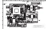
MCU 3.3V REG
Bluetooth 3.3V REG
DC-DC 5V/1A
+22V
GND
+22V
+22V
GND
GND
Pairing SW
Update
MOSI
MISO
CSB
B3V3
CLK
GND
WPU_3V3
MARKs for SMD
Controlled Impedance: 50 ohms
1
2
3
RX801
Q802
3904
D801
6.8V
L803
FB600
0603
L804
FB600
0603
L805
FB600
0603
R828
1K
1
AU_REF
2
NC
3
VDD_AUDIO
4
NC
5
NC
6
NC
7
NC
8
VDD_AUDIO_DRV
9
LINEOUT_AN
10
LINEOUT_AP
11
VDD_BT_RADIO
12
BT_RF
13
VDD_BT_LO
14
VDD_AUX
15
VDD_AUX_1V8
16
VDD_AUX_1V8
17
VDD_ANA_O
18
XTAL_OUT
19
XTAL_IN
20
NC
21
PIO15/UART_TX
22
PIO12/I2C_WP
23
PIO14/UART_RX
24
SPI_CSB/PCM_SYNC
25
PIO10/I2C_SCL
26
PIO11/I2C_SDA
27
PIO16
28
SPI_MISO/PCM_OUT
29
SPI/PCM
30
SPI_MOSI/PCM_IN
31
PIO13
32
PIO17
33
VDD_PADS1
34
SPI_CLK/PCM_CLK
35
RST#
36
LED1
37
LED0
38
VDD_DIG
39
VREGIN_DIG
40
VREG_EN
41
BYP_OUT
42
BYP_IN
43
NC
44
SMP_VIN
45
SMP_VIN
46
VSS_1V8
47
LX_1V8
48
SMP_VIN
49
SMP_VIN
50
LX_1V35
51
VSS_1V35
52
1V35_SENSE
53
1V8_SENSE
54
SMP_VIN
55
NC
56
NC
57
PIO7/SDA
58
PIO9/UART_CTS
59
PIO0/UART_RX
60
PIO1/UART_TX
61
PIO8/UART_RTS
62
PIO6/SCL
63
VDD_PADS2
64
PIO21
65
PIO18
66
LED2
67
LINE_AN
68
LINE_AP
69
IC802
CSRA65700
1
OUT
2
GND
3
IN
4
GND
IC801
BPF-2520
ANT
PCB_ANT-2.4G
L806
0R
1
A0
2
A1
3
A2
4
VSS
5
SDA
6
SCL
7
WP
8
VCC
IC803
GT24C128
L807
4.7uH
L808
4.7uH
Y801
26M
R819
220R
L810
10uH/12A
R831
1M
R837
5.6K
R840
NC
R844
3R3
R845
3R3
1
2
CN805
2P/3.96
SUBWOOFER
R860
NC
R861
NC
C866
10nF
C865
10nF
C858
0.1uF
C856
0.1uF
C859
1uF
50V
C839
1uF
C843
1uF
C844
1nF
C845
1nF
C836
NC
C837
NC
R817 220R
C816
1uF
C820
10uF
C819
0.1uF
C825
470nF
C822
0.1uF
C818
0.1uF
C821
0.1uF
C840
100pF
C841
100pF
R820
NC
R824
NC
C830
10nF
C838
0.1uF
16V
X7R
R826
1K
R827
1K
R829
1K
R830
1K
R821
4.7K
R822
2.2K
R823
2.2K
C824
0.1uF
C817
0.1uF
C829
10uF
R825
10K
C835
15pF
C823
1.5pF
R849
100R
C872
0.1uF
C804
0.1uF
R854
470K
R855
100K
R856
1K
R857
47K
L812
FB600
0603
C803
0.1uF
R803
150K
1%
C807
5pF
R801
220K
R802
43K
R807
49.9K
R806
100K
R810
12K1%
R808
62K 1%
C810
1nF
C811
0.1uF
C806
10uF
C812
10uF
R811
10K
1
2
3
4
5
6
CN804
6pin-P2.5
R846
10K
R805
4.7K
C852
1uF
PAD
Thermal
1
MODSEL
2
SDZ
3
FAULTZ
4
INPR
5
INNR
6
PLIMIT
7
GVDD
8
GAIN/SLV
9
GND
10
INPL
11
INNL
12
MUTE
13
AM2
14
AM1
15
AM0
16
SYNC
17
AVCC
18
PVCC
19
PVCC
20
BSNL
21
OUTNL
22
GND
23
OUTPL
24
BSPL
25
GND
26
BSNR
27
OUTNR
28
GND
29
OUTPR
30
BSPR
31
PVCC
32
PVCC
IC805
TPA3116D2
C857
1uF
50V
R858
10R
C862
330pF
R859
10R
C873
330pF
C874
220nF
C875
220nF
C876
220nF
C877
220nF
EC801
470UF/35V
C878
1nF
C863
1nF
C864
1nF
C879
1nF
C846
0.1uF
C847
0.1uF
F801
1A/63V
1
VIN
2
GND
3
EN
4
NC
5
VOUT
IC807
BL9198-33BAPRN
C849
0.1uF
C853
0.1uF
C851
10uF
C854
10uF
R812
1M
R839
10K
1
VIN
2
GND
3
EN
4
NC
5
VOUT
IC808
BL9198-33BAPRN
C855
0.1uF
C880
0.1uF
C881
10uF
C882
10uF
R862
1M
R863
10K
C884
0.1uF
C885
10uF
R865
33R
R866
33R
R867
33R
C887
33pF
C888
33pF
C889
33pF
+
-
3
2
1
IC810-A
DIO2032
+
-
5
6
7
IC810-B
DIO2032
8
4
IC810-C
DIO2032
C890
0.1uF
C891
10uF
R815
2.2K
R873
2.2K
C813
10uF
R889
100R
R841
100R
C814
2.2uF
C827
4.7uF
C832
4.7uF
C833
2.2uF
R878
47K
R879
47K
R832
1M
R833
1K
R834
1M
C801 0.1uF
L811
10uH/12A
1
SW
2
EN
3
COMP
4
FB
5 GND
6 RT
7 VIN
8 BS
9
PAD
IC806
EML3193B
R804
300R
1%
R813
10R
C809
1nF
R850
0R
R851
1K
C867
470nF
R847
1K
R864
1K
R872
1K
EC804
22uF
35V
EC803
47uF
16V
EC802
470UF/35V
1
PD4/TIM2
2
PD5/AIN5
3
PD6/AIN6
4
NRST
5
OSCIN/PA1
6
OSCOUT/PA2
7
VSS
8
VCAP
9
VDD
10
TIM2/PA3
11
PB5/I2C_SDA
12
PB4/I2C_SCL
13
PC3/TIM1
14
PC4/TIM1
15
PC5/SPI_SCK
16
PC6/SPI_MOSI
17
PC7/SPI_MISO
18
PD1/SWIM
19
PD2/AIN3
20
PD3/TIM2
IC804
STM8S003F3
R852
1K
C848
0.1uF
C868
2.2uF
L801
15uH/1A
R893 1K
1
CPVDD
2
CAPP
3
CPGND
4
CAPM
5
VNEG
6
OUTL
7
OUTR
8
AVDD
9
AGND
10
DEMP
11
FLT
12
SCK
13
BCK
14
DIN
15
LRCK
16
FMT
17
XSMT
18
LDOO
19
DGND
20
DVDD
IC809
PCM5100A
R869
2.2K
R870
NC
C894
56nF
C896
10uF
C899
0.1uF
C800
2.2uF
C901
2.2uF
C893
56nF
R876
4.7K
C897
10nF
L815
FB600
0603
L819
FB600
0603
C902
0.1uF
C903
10uF
L820
FB600
0603
C904
0.1uF
C906
10uF
C892
0.1uF
C898
0.1uF
C802
0.1uF
R835
3K
R868
5.6K
C815
2.2uF
C831
10nF
C805
10nF
R874
100K
R875
3.9K
D802
B340
C808
330pF
C826
2.2uF
R838
33R
R880
33R
R882
33R
C842
33pF
C869
33pF
C870
33pF
R884
100R
EC805
100uF
10V
R888
0R
C871
0.1uF
C883
10uF
L809
FB600
0603
C834
NC
LED802
Red
LED801
Green
R895
10R
R896
10R
S801
C861
22uF
1
2
3
4
5
6
7
8
9
10
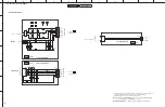
CN800
10P/1.0
TP1
TP2
TP3
TP4
R814 1K
Q800
2N3904
Q801
2N3904
R881
47K
R885
47K
C828
10nF
R886
47K
BT_RST
BT_RF_TEST
R848
100K
R877
1K
1
AI-HOLE
1
AI-HOLE
R883
1K
1
2
CN1
1
2
CN2
1
1
+5V
BCK
DA
WS
PVCC_22V
B3V3
M3V3
PVCC_22V
PVCC_22V
B3V3
M3V3
I2S_SPI
I2S_DATA
I2S_BCK
SPI_MOSI
SPI/PCM
I2S_LRCK
SWIMI
I2S_LRCK
I2S_DATA
SPI_MOSI
I2S_BCK
SPI/PCM
DC_DET
MUTE_AMP
FAULTZ_AMP
STBY_AMP
VREG_EN
RST_BT
I2S_LRCK
I2S_DATA
I2S_BCK
MUTE_BT
UART_TX
PRI
LED_R
B3V3
B3V3
M3V3
SWIM
RST
LED_G
LED0_BT
LED1_BT
RESET
PAIRING
PAIRING_SW
I2S_BCK
I2S_DATA
I2S_LRCK
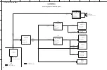
AC 90~264V
AC-OUT
AC-OUT
AC INLET BOARD
50/60Hz
TO SMPS
2
1
CN605
AC SOCKET
1
AC600
1
AC601
DRIVER
SUBWOOFER
PAIRING
STANDBY
indicator
indicator
SUB
(AC)
SUB
AC IN
(AC)
AMP
to Power supply unit
Writing port
to Power supply unit
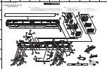
NS-WSW42
A
B
C
D
E
F
G
H
I
J
1
2
3
4
5
6
7
YAS-CU207/ATS-CU2070/NS-WSW42
45
AMP, SUB (AC)
Содержание YAS-207
Страница 8: ...Top view Rear view NS WSW42 8 YAS CU207 ATS CU2070 NS WSW42 YAS CU207 ATS CU2070 NS WSW42...
Страница 10: ...B model G model V model J model 10 YAS CU207 ATS CU2070 NS WSW42 YAS CU207 ATS CU2070 NS WSW42...
Страница 30: ...MEMO 30 YAS CU207 ATS CU2070 NS WSW42 YAS CU207 ATS CU2070 NS WSW42...