FUEL INJECTION SYSTEM
7-32
EAS27400
TROUBLESHOOTING METHOD
The engine operation is not normal and the
engine trouble warning light comes on.
1. Check:
●
Fault code number
▼▼▼▼▼▼▼▼▼▼▼▼▼▼▼▼▼▼▼▼▼▼▼▼▼▼▼▼▼▼▼▼
a. Check the fault code number displayed on
the meter.
b. Identify the faulty system with the fault code.
Refer to “Self-Diagnostic Funciton table”.
c. Identify the probable cause of the malfunc-
▲▲▲▲▲▲▲▲▲▲▲▲▲▲▲▲▲▲▲▲▲▲▲▲▲▲▲▲▲▲▲▲
tion. Refer to “Fault code table”.
2. Check and repair the probable case of mal-
function.
3. Perform the fuel injection system reinstate-
ment action.
Refer to “Reinstatement method” of table in
“TROUBLESHOOTING DETAILS” on page
7-41.
4. Turn the main switch to “OFF” and back to
“ON”, then check that no fault code number is
displayed.
NOTE:
If fault codes are displayed, repeat steps (1) to
(4) until no fault code number is displayed.
5. Erase the malfuction history in the diagnostic
mode. Refer to “Sensor operation table (Di-
agnostic code No.62)”.
NOTE:
Turning the main switch to “OFF” will not erase
the malfuction history.
The engine operation is not normal but the
engine trouble warning light does not come
on.
1. Check the operation of following sensors and
actuators in the Diagnostic mode. “ Refer to
“Sensor operation table” and “Actuator oper-
ation table”.
If a malfunction is detected in the sensors or
actuators, repair or replace all faulty parts.
If no malfunction is detected in the sensors
and actuators, check and repair inner parts of
the engine.
EAS27440
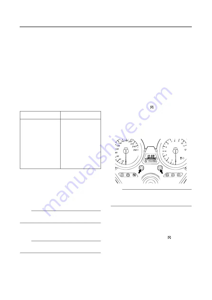
DIAGNOSTIC MONITORING MODE
Setting the diagnostic monitoring mode
1. Turn the main switch to “OFF” and set the en-
gine stop switch to “
”.
2. Disconnect the wire harness coupler from the
fuel pump.
3. Press the SELECT button and RESET button
simultaneously, turn the main switch “ON”,
and keep switch pressed for at least 8 sec-
onds.
NOTE:
●
All displays on the meter disappear except the
clock and tripmeter displays.
●
“dIAG” appears on the clock LCD.
4. Press the SELECT button to select the CO
adjustment mode “CO” or the diagnostic
monitoring mode “dIAG”.
5. After selecting “CO”, press the SELECT and
RESET buttons simultaneously for at least 2
seconds.
6. Set the engine stop switch to “
”.
7. Select the diagnostic monitoring code num-
ber that applies to the item that was verified
with the fault code number by pressing the
SELECT and RESET buttons.
Fault code No.
No fault code No.
Check and repair.
Refer to
SHOOTING DETAILS”
on page 7-41.
Monitor the opera-
tion of the sensors
and actuators in the
diagnostic mode.
Refer to “Sensor
operation table” and
“Actuator operation
table”.
Check and repair.
Содержание XJR1300 2007
Страница 1: ...SERVICE MANUAL XJR1300 W 5WM 28197 E0 2007 ...
Страница 2: ......
Страница 8: ......
Страница 47: ...LUBRICATION POINTS AND LUBRICANT TYPES 2 24 ...
Страница 48: ...LUBRICATION DIAGRAMS 2 25 EAS28860 LUBRICATION DIAGRAMS ...
Страница 50: ...LUBRICATION DIAGRAMS 2 27 ...
Страница 51: ...LUBRICATION DIAGRAMS 2 28 1 Drive axle 2 Push rod 3 Main axle 4 Camshaft 5 Crankshaft ...
Страница 52: ...LUBRICATION DIAGRAMS 2 29 ...
Страница 53: ...LUBRICATION DIAGRAMS 2 30 1 Nozzle 2 Bypass valve 3 Oil filter element 4 Relief valve ...
Страница 54: ...CABLE ROUTING 2 31 EAS20430 CABLE ROUTING ...
Страница 56: ...CABLE ROUTING 2 33 ...
Страница 58: ...CABLE ROUTING 2 35 ...
Страница 60: ...CABLE ROUTING 2 37 ...
Страница 62: ...CABLE ROUTING 2 39 ...
Страница 64: ...CABLE ROUTING 2 41 ...
Страница 66: ...CABLE ROUTING 2 43 ...
Страница 68: ...CABLE ROUTING 2 45 ...
Страница 70: ...CABLE ROUTING 2 47 ...
Страница 185: ...CAMSHAFTS 5 12 Refer to ADJUSTING THE VALVE CLEAR ANCE on page 3 4 10 Install Timing plate cover ...
Страница 205: ...GENERATOR 5 32 b Measure the stator coil resistances 1 2 ...
Страница 240: ...STARTER CLUTCH 5 67 1 3 2 New ...
Страница 260: ...FUEL TANK 6 3 fuel hose end in the direction of the arrow 1 ...
Страница 269: ...THROTTLE BODIES 6 12 ...
Страница 270: ...AIR INDUCTION SYSTEM 6 13 EAS27040 AIR INDUCTION SYSTEM 1 2 3 4 4 5 4 4 3 2 1 1 2 4 3 ...
Страница 274: ...AIR INDUCTION SYSTEM 6 17 ...
Страница 277: ......
Страница 278: ...IGNITION SYSTEM 7 1 EAS27090 IGNITION SYSTEM EAS27110 CIRCUIT DIAGRAM ...
Страница 282: ...ELECTRIC STARTING SYSTEM 7 5 EAS27160 ELECTRIC STARTING SYSTEM EAS27170 CIRCUIT DIAGRAM ...
Страница 288: ...CHARGING SYSTEM 7 11 EAS27200 CHARGING SYSTEM EAS27210 CIRCUIT DIAGRAM ...
Страница 289: ...CHARGING SYSTEM 7 12 1 Generator 2 Main switch 4 Main fuse 7 Battery ...
Страница 291: ...CHARGING SYSTEM 7 14 ...
Страница 292: ...LIGHTING SYSTEM 7 15 EAS27240 LIGHTING SYSTEM EAS27250 CIRCUIT DIAGRAM ...
Страница 295: ...LIGHTING SYSTEM 7 18 ...
Страница 296: ...SIGNALING SYSTEM 7 19 EAS27270 SIGNALING SYSTEM EAS27280 CIRCUIT DIAGRAM ...
Страница 302: ...FUEL INJECTION SYSTEM 7 25 EAS27330 FUEL INJECTION SYSTEM EAS27340 CIRCUIT DIAGRAM ...
Страница 342: ...FUEL PUMP SYSTEM 7 65 EAS27580 FUEL PUMP SYSTEM EAS27590 CIRCUIT DIAGRAM ...
Страница 345: ...FUEL PUMP SYSTEM 7 68 ...
Страница 346: ...IMMOBILIZER SYSTEM 7 69 EAS27640 IMMOBILIZER SYSTEM EAS27650 CIRCUIT DIAGRAM ...
Страница 355: ...IMMOBILIZER SYSTEM 7 78 ...
Страница 356: ...ELECTRICAL COMPONENTS 7 79 EAS27970 ELECTRICAL COMPONENTS EAS5UXB011 1 3 4 5 7 8 6 10 11 12 13 14 15 15 16 17 18 2 9 ...
Страница 361: ...ELECTRICAL COMPONENTS 7 84 a b Br R Br R ...
Страница 382: ......
Страница 383: ......
Страница 384: ...YAMAHA MOTOR CO LTD 2500 SHINGAI IWATA SHIZUOKA JAPAN ...


