


9-4
E
TRBL
ANLS
1
2
3
4
5
6
7
8
9
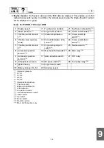
7.
ECM record data graph:
When a malfunction occurs in the ETV system, 4 seconds (2 seconds
before and after the malfunction) of recorded data are saved in the ECM. This data can be dis-
played on a graph using the
“
ECM record data graph
”
of the Data logger function.
When the communication cable is used to connect a computer to the ECM, the ECM record
data can be saved and viewed on the computer.
The saved ECM record data can also be viewed offline.
Items: For FX SHO, FX Cruiser SHO
(*1)
: APS 1
(*2)
: APS 2
(*3)
: TPS 1
(*4)
: TPS 2
(*5)
: Intake air pressure
(*6)
: Target TPS voltage
This item shows the target output voltage of the TPS.
This value is the control voltage that the ECM requires to set the target opening angle of the throttle
valve.
(*7)
: Reference TPS voltage
This item shows the criterion output voltage of the TPS.
This value is used to detect the TPS output voltage during engine operation.
(*8)
: Reference APS voltage
This item shows the criterion output voltage of the APS.
This value is used to detect the APS output voltage when the throttle lever is opened.
(*9)
: Target TPS voltage for Idle Speed Control
ECM controls the engine idle speed by using the throttle valve attached to the TPS.
This target voltage is used by the ECM to achieve the target opening angle of the throttle valve at
the engine idle speed.
(*10)
: Engine stop mode with switch
(*11)
: Engine shut-off switch
(*12)
: Main and fuel pump relay
(*13)
: Thermoswitch
(*14)
: Oil pressure switch
NOTE:
To display the displays and graphs, refer to the YDIS (Ver. 1.30) Instruction Manual.
1 Engine speed
10 Ref. TPS voltage
(*7)
19 No-Wake mode
2 Accelerator position
sensor 1
(*1)
11 Ref. acc. pos. sensor
voltage
(*8)
20 Low-RPM mode
3 Accelerator position
sensor 2
(*2)
12 Target TPS voltage for
ISC
(*9)
21 Engine stop lanyard
switch
(*11)
4 Steering sensor
13 Engine stop mode
22 Main relay
(*12)
5 Throttle position sensor
1
(*3)
14 Engine start mode
23 ETV relay
6 Throttle position sensor
2
(*4)
15 Engine stop mode with
SW
(*10)
24 Overheat
thermoswitch
(*13)
7 Intake pressure
(*5)
16 OTS mode
25 Oil press switch
(*14)
8 Battery voltage
17 Cruise assist mode
26 Warning
9 Target TPS voltage
(*6)
18 Reverse mode
27 ETV limit
Содержание WaveRunner FX SHO
Страница 1: ...SERVICE MANUAL FX SHO WaveRunner F1W 28197 1K 11 FX Cruiser SHO LIT 18616 03 12 LIT186160312 ...
Страница 58: ...1 53 E GEN INFO MEMO Technical tips ...
Страница 82: ...2 23 E SPEC MEMO Cable and hose routing ...
Страница 110: ...3 27 E CHK ADJ MEMO General ...
Страница 243: ...5 118 E POWR 1 2 3 4 5 6 7 8 9 MEMO Cooling water ...
Страница 275: ...6 30 E JET PUMP 1 2 3 4 5 6 7 8 9 MEMO Intermediate housing ...
Страница 353: ...E ELEC 1 2 3 4 5 6 7 8 9 7 76 MEMO Indication system ...
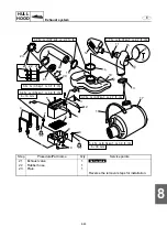
Страница 410: ...8 55 E HULL HOOD MEMO Deck and hull ...
Страница 429: ...9 18 E TRBL ANLS 1 2 3 4 5 6 7 8 9 MEMO Engine unit trouble analysis ...
Страница 431: ......
Страница 432: ...YAMAHA MOTOR CORPORATION USA Printed in USA Jan 2008 0 0 1 CR E ...


