background image

–24–

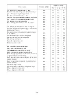
Steering shaft assembly and frame

M8

21

2.1

15

Steering wheel and steering shaft assembly

M12

35

3.5

25

Steering knuckle and front upper arm 

M12 

30

3.0

22

Steering knuckle and front lower arm 

M12 

30

3.0

22

Tie-rod locknut

M12

40

4.0

29

Steering knuckle and tie-rod 

M12

39

3.9

28

Front arm protector and front lower arm

M6

7

0.7

5.1

Seat belt buckle and support frame

M10

59

5.9

43

Seat belt and frame

M10

59

5.9

43

Seat belt and side frame (enclosure)

7/16

59

5.9

43

Front wheel and front wheel hub 

M10 

55

5.5

40

Front wheel hub and constant velocity joint 

M24

350

35.0

255

Steering knuckle and brake disc guard 

M6 

7

0.7

5.1

Front brake caliper and front wheel hub 

M10

48

4.8

35

Front brake hose union bolt 

M10 

27

2.7

19

Front brake hose holder and steering knuckle

M6

7

0.7

5.1

Front brake hose holder and front upper arm

M6

7

0.7

5.1

Front brake hose and frame

M6

7

0.7

5.1

Front brake hose holder and frame

M6

7

0.7

5.1

Front brake pad holding bolt

M8

18

1.8

13

Front brake disc and front wheel hub 

M8

30

3.0 

22

Front brake caliper bleed screw

M6

6

0.6 

4.3

Rear wheel and rear wheel hub

M10

55

5.5

40

Rear wheel hub and constant velocity joint 

M24

350

35.0

255

Rear brake hose and frame

M6

7

0.7

5.1

Brake pipe and brake master cylinder

M10

19

1.9

13

Brake pipe and rear brake hose

M10

19

1.9

13

Pedal assembly and frame

M8

16

1.6

11

Brake master cylinder and pedal assembly

M8

16

1.6

11

Secondary brake master cylinder kit stopper bolt

M6

9

0.9

6.5

Brake rod locknut

M8

17

1.7

12

Rear brake disc and brake disc boss

M6

10

1.0 

7.2

Rear brake pad holding bolt 

M8

17

1.7

12

Rear brake caliper and final drive pinion gear bear-
ing housing

M10 40

4.0 

29

Rear brake hose union bolt 

M10 

27

2.7

19

Parking brake case and rear brake caliper

M8

22

2.2

16

Parking brake lever assembly and frame

M6

7

0.7

5.1

Rear brake caliper bleed screw

M6

5

0.5

3.6

Cargo bed release lever

M6

7

0.7

5.1

M8

26

2.6

19

Gas spring assembly and gas spring assembly 
bracket

M8

16

1.6

11

Part to be tightened

Thread size

Tightening torque

Nm

m · kg

ft · lb

Содержание Rhino YXR66FAV

Страница 1: ...5UG F8107 71 YXR66FAV ASSEMBLY MANUAL MANUEL DE MONTAGE...

Страница 2: ...PROPOS Ce Manuel de montage contient les instruc tions n cessaires au montage en bonne et due forme de ce v hicule Yamaha avant sa livrai son au client Certaines pi ces du v hicule ayant t d pos es l...

Страница 3: ...art e g 5 0 20 5 mm 0 20 in FBA00005 SYMBOLES UTILIS S DANS LE MANUEL DE MONTAGE Les symboles suivants ont t adopt s en vue de simplifier les explications 1 Liquide de remplissage 2 Lubrifiant 3 Outil...

Страница 4: ...rticles to fly off Protect hands and feet by wearing safety gloves and shoes FBA00006 PR PARATIFS Certaines fournitures ex huiles graisses et essuyeurs et un espace de travail suffisam ment spacieux s...

Страница 5: ...ly lift the vehicle so there is no danger of it falling 3 4 Remove the packing frame 4 4 FBA00008 D BALLAGE 1 Retirer les sangles 1 2 Retirer les sangles 2 3 Soulever l arri re du v hicule retirer le...

Страница 6: ...r seat 4 Owner s tool kit tire pressure gauge located in the space beside the battery FBA00009 EMPLACEMENT DES PI CES 1 Plaques de protection 2 Sac en plastique 1 3 Manuel du propri taire situ au fond...

Страница 7: ...gauge 1 Owner s tool kit 2 Tire pressure gauge 1 2 FBA00010 1 Plaques de protection 1 Plaque de protection A 2 Plaque de protection B 3 Plaque de protection C 2 Sac en plastique 1 1 Vis plaques de pro...

Страница 8: ...oil level Checking the brake fluid level Checking the differential gear oil level Bleeding the hydraulic brake system Checking the final gear oil level Adjusting the select lever control cable and sh...

Страница 9: ...niveau du liquide de frein Contr le du niveau d huile de diff rentiel Purge du circuit des freins hydrauliques Contr le du niveau d huile de couple conique arri re R glage du c ble de commande du s le...

Страница 10: ...form the setup procedures in the order indicated by the numbers Always follow the order as shown FBA00012 MONTAGES EFFECTUER N B _ Avant le montage il convient de gonfler les quatre pneus la pression...

Страница 11: ...ping T R Bolt 7 Nm 0 7 m kg 5 1 ft lb 1 1 S 1 2 1 S 1 3 2 V 14 4 2 V 14 d 6 0 24 16 0 63 5 1 S 1 6 2 V 4 2 3 4 1 4 3 A A B 7 7 a 5 6 FBA00039 1 PLAQUES DE PROTECTION A Serrer les vis au couple sp cifi...

Страница 12: ...he predelivery service in the order indicated by the letters Always follow the order as shown FBA00101 R GLAGES ET ENTRETIENS AVANT LIVRAISON Effectuer les entretiens avant livraison dans l ordre indi...

Страница 13: ...is not neces sary FBA00102 A CONTR LE ET CHARGEMENT DE LA BATTERIE 1 Contr ler On peut contr ler l tat de charge d une batterie sans entretien MF en mesurant la tension entre ses cosses en circuit ouv...

Страница 14: ...91 kPa 0 91 kgf cm2 13 psi FBA00105 B CONTR LE DE LA PRESSION DE GONFLAGE DES PNEUS AVERTISSEMENT _ Respecter les points suivants Pression de gonflage recommand e Avant 70 kPa 0 70 kgf cm2 10 psi Arr...

Страница 15: ...S qt FBA00106 C VIDANGE DU CARBURANT 1 D poser si ge du conducteur si ge du passager console 2 Placer un chiffon sous la durite de vidange du carburateur afin de prot ger le carter de toute coulure de...

Страница 16: ...ile moteur lubrifie galement l embrayage et une huile de type inad quat ou des additifs pourraient faire patiner ce dernier Il convient donc de ne pas ajouter d additifs chimiques ni d uti liser des h...

Страница 17: ...ne surface de niveau 2 D poser vis de l orifice de remplissage d huile 1 3 Contr ler niveau d huile de couple conique L huile de couple conique doit atteindre le bord du goulot de remplissage Sous le...

Страница 18: ...istance decreased 4 Mettre le moteur en marche le faire chauf fer pendant quelques minutes puis le cou per 5 Contr ler niveau du liquide de refroidissement N B _ Laisser le liquide de refroidissement...

Страница 19: ...decreased 4 a FBA00121 I R GLAGE DU R GIME DE RALENTI DU MOTEUR 1 Mettre le moteur en marche et le laisser chauffer pendant quelques minutes 2 D poser si ge du conducteur si ge du passager console 3...

Страница 20: ...ee play is decreased T R Locknut 17 Nm 1 7 m kg 12 ft lb c Serrer le contre crou N B _ Apr s avoir r gl le jeu de c ble des gaz actionner plusieurs reprises la p dale d acc l rateur et s assurer que l...

Страница 21: ...e play is increased Direction c Free play is decreased FBA00129 L R GLAGE DU CONTACTEUR DE FEU STOP N B _ Le contacteur du feu stop est actionn par le mouvement de la p dale de frein Le r glage est co...

Страница 22: ...le si ge du passager si ge du conducteur FBA00131 N CONTR LE DU NIVEAU DU LIQUIDE DE FREIN 1 Placer le v hicule sur une surface de niveau N B _ Le sommet du r servoir de liquide de frein doit tre l ho...

Страница 23: ...CIRCUIT DES FREINS HYDRAULIQUES AVERTISSEMENT _ Purger le circuit des freins hydrauliques dans les cas suivants le circuit a t d mont une durite ou un tuyau de frein a t des serr ou d pos le niveau d...

Страница 24: ...R GLAGE DU C BLE DE COMMANDE DU S LECTEUR DE MARCHE ET DE LA TIGE DE S LECTEUR ATTENTION Avant de changer de rapport il faut arr ter le v hicule et l cher la p dale d acc l ra teur Sinon la bo te de...

Страница 25: ...beam is raised Turning out Headlight beam is low ered FBA00136 R R GLAGE DES AMORTISSEURS ARRI RE AVERTISSEMENT _ Toujours r gler la pr contrainte de ressort des deux amortisseurs sur la m me valeur U...

Страница 26: ...er bit Phillips head and slotted head 1pc 5 Pliers 1pc 6 Wrench 10 12 1pc 7 Wrench 14 17 1pc FBA00200 APPENDICE DONN ES D ENTRETIEN R gime de ralenti du moteur 1 450 1 550 tr mn Bougie s Type fabrican...

Страница 27: ...M10 55 5 5 40 Differential gear oil filler plug M14 23 2 3 17 Differential gear oil drain plug M10 10 1 0 7 2 Universal joint yoke and drive pinion gear M14 62 6 2 45 Gear motor and differential gear...

Страница 28: ...6 7 0 7 5 1 Front brake pad holding bolt M8 18 1 8 13 Front brake disc and front wheel hub M8 30 3 0 22 Front brake caliper bleed screw M6 6 0 6 4 3 Rear wheel and rear wheel hub M10 55 5 5 40 Rear wh...

Страница 29: ...M6 7 0 7 5 1 Upper instrument panel and frame M6 7 0 7 5 1 Side frame enclosure and frame M10 64 6 4 46 Support frame enclosure and frame M10 64 6 4 46 Left support frame enclosure and right support...

Страница 30: ...e barre stabilisatrice et triangle de suspension arri re inf rieur M10 56 5 6 40 Carter de diff rentiel et cadre M10 55 5 5 40 Bouchon de remplissage du carter de diff rentiel M14 23 2 3 17 Bouchon de...

Страница 31: ...t M24 350 35 0 255 Fus e de direction et prot ge disque de frein M6 7 0 7 5 1 trier de frein avant et moyeu de roue avant M10 48 4 8 35 Vis de raccord de durite de frein avant M10 27 2 7 19 Support de...

Страница 32: ...e chargement M6 7 0 7 5 1 C ble du hayon et caisse de chargement M6 7 0 7 5 1 C ble du hayon et hayon M6 7 0 7 5 1 Calandre et protection avant M6 7 0 7 5 1 Protection avant et cadre M10 32 3 2 23 M12...

Страница 33: ......

Страница 34: ...YAMAHA MOTOR CO LTD 2500 SHINGAI IWATA SHIZUOKA JAPAN PRINTED IN THE NETHERLANDS 2005 07 2 0 1 CR E F...

Отзывы: