


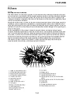


EAS20071
IMPORTANT
This manual was produced by the Yamaha Motor Company, Ltd. primarily for use by Yamaha deal-
ers and their qualified mechanics. It is not possible to include all the knowledge of a mechanic in one
manual. Therefore, anyone who uses this book to perform maintenance and repairs on Yamaha
vehicles should have a basic understanding of mechanics and the techniques to repair these types
of vehicles. Repair and maintenance work attempted by anyone without this knowledge is likely to
render the vehicle unsafe and unfit for use.
This model has been designed and manufactured to perform within certain specifications in regard
to performance and emissions. Proper service with the correct tools is necessary to ensure that the
vehicle will operate as designed. If there is any question about a service procedure, it is imperative
that you contact a Yamaha dealer for any service information changes that apply to this model. This
policy is intended to provide the customer with the most satisfaction from his vehicle and to conform
to federal environmental quality objectives.
Yamaha Motor Company, Ltd. is continually striving to improve all of its models. Modifications and
significant changes in specifications or procedures will be forwarded to all authorized Yamaha deal-
ers and will appear in future editions of this manual where applicable.
TIP
• This Service Manual contains information regarding periodic maintenance to the emission control
system. Please read this material carefully.
• Designs and specifications are subject to change without notice.
EAS20081
IMPORTANT MANUAL INFORMATION
Particularly important information is distinguished in this manual by the following notations.
This is the safety alert symbol. It is used to alert you to potential per-
sonal injury hazards. Obey all safety messages that follow this symbol
to avoid possible injury or death.
A WARNING indicates a hazardous situation which, if not avoided,
could result in death or serious injury.
A NOTICE indicates special precautions that must be taken to avoid
damage to the vehicle or other property.
A TIP provides key information to make procedures easier or clearer.
WARNING
Содержание R6 2009
Страница 1: ...SERVICE MANUAL YZFR6Y C 13S 28197 11 LIT 11616 22 51 2009 ...
Страница 6: ......
Страница 8: ......
Страница 60: ...LUBRICATION SYSTEM CHART AND DIAGRAMS 2 29 EAS20410 LUBRICATION DIAGRAMS 1 2 3 4 ...
Страница 62: ...LUBRICATION SYSTEM CHART AND DIAGRAMS 2 31 1 2 3 4 8 7 6 5 ...
Страница 64: ...LUBRICATION SYSTEM CHART AND DIAGRAMS 2 33 1 2 3 4 5 ...
Страница 65: ...LUBRICATION SYSTEM CHART AND DIAGRAMS 2 34 1 Oil cooler 2 Oil filter 3 Oil pipe 4 Oil pump 5 Oil strainer ...
Страница 66: ...LUBRICATION SYSTEM CHART AND DIAGRAMS 2 35 1 5 4 3 2 ...
Страница 68: ...LUBRICATION SYSTEM CHART AND DIAGRAMS 2 37 3 1 2 5 4 ...
Страница 70: ...LUBRICATION SYSTEM CHART AND DIAGRAMS 2 39 1 3 2 ...
Страница 71: ...LUBRICATION SYSTEM CHART AND DIAGRAMS 2 40 1 Oil pipe 2 Main axle 3 Drive axle ...
Страница 72: ...COOLING SYSTEM DIAGRAMS 2 41 EAS20420 COOLING SYSTEM DIAGRAMS 1 2 3 4 ...
Страница 73: ...COOLING SYSTEM DIAGRAMS 2 42 1 Radiator inlet hose 2 Radiator inlet pipe 3 Thermostat outlet hose 4 Radiator ...
Страница 74: ...COOLING SYSTEM DIAGRAMS 2 43 A A 2 1 3 4 5 6 7 8 6 13 8 9 15 14 9 10 11 12 ...
Страница 76: ...CABLE ROUTING 2 45 EAS20430 CABLE ROUTING ...
Страница 78: ...CABLE ROUTING 2 47 ...
Страница 80: ...CABLE ROUTING 2 49 ...
Страница 82: ...CABLE ROUTING 2 51 ...
Страница 84: ...CABLE ROUTING 2 53 ...
Страница 86: ...CABLE ROUTING 2 55 ...
Страница 88: ...CABLE ROUTING 2 57 ...
Страница 90: ...CABLE ROUTING 2 59 A A ...
Страница 92: ...CABLE ROUTING 2 61 ...
Страница 95: ......
Страница 135: ......
Страница 206: ...CHAIN DRIVE 4 71 1 2 3 a a New ...
Страница 209: ......
Страница 240: ...PICKUP ROTOR 5 31 ...
Страница 286: ...TRANSMISSION 5 77 ...
Страница 290: ...RADIATOR 6 3 b Apply 100 kPa 14 50 psi 1 0 kg cm2 of pressure c Measure the indicated pressure with the gauge ...
Страница 300: ...WATER PUMP 6 13 ...
Страница 316: ...AIR INDUCTION SYSTEM 7 15 EAS27040 AIR INDUCTION SYSTEM 2 1 2 4 3 4 3 6 4 5 A A ...
Страница 323: ......
Страница 324: ...IGNITION SYSTEM 8 1 EAS27090 IGNITION SYSTEM EAS27110 CIRCUIT DIAGRAM ...
Страница 330: ...ELECTRIC STARTING SYSTEM 8 7 EAS27160 ELECTRIC STARTING SYSTEM EAS27170 CIRCUIT DIAGRAM ...
Страница 336: ...CHARGING SYSTEM 8 13 EAS27200 CHARGING SYSTEM EAS27210 CIRCUIT DIAGRAM ...
Страница 337: ...CHARGING SYSTEM 8 14 1 AC magneto 2 Rectifier regulator 6 Main fuse 7 Battery 11 Engine ground ...
Страница 339: ...CHARGING SYSTEM 8 16 ...
Страница 340: ...LIGHTING SYSTEM 8 17 EAS27240 LIGHTING SYSTEM EAS27250 CIRCUIT DIAGRAM ...
Страница 344: ...SIGNALING SYSTEM 8 21 EAS27270 SIGNALING SYSTEM EAS27280 CIRCUIT DIAGRAM ...
Страница 351: ...SIGNALING SYSTEM 8 28 ...
Страница 352: ...COOLING SYSTEM 8 29 EAS27300 COOLING SYSTEM EAS27310 CIRCUIT DIAGRAM ...
Страница 355: ...COOLING SYSTEM 8 32 ...
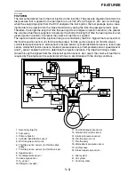
Страница 356: ...FUEL INJECTION SYSTEM 8 33 EAS27330 FUEL INJECTION SYSTEM EAS27340 CIRCUIT DIAGRAM ...
Страница 395: ...FUEL INJECTION SYSTEM 8 72 ...
Страница 396: ...FUEL PUMP SYSTEM 8 73 EAS27550 FUEL PUMP SYSTEM EAS27560 CIRCUIT DIAGRAM ...
Страница 399: ...FUEL PUMP SYSTEM 8 76 ...
Страница 400: ...ELECTRICAL COMPONENTS 8 77 EAS27970 ELECTRICAL COMPONENTS ...
Страница 402: ...ELECTRICAL COMPONENTS 8 79 1 5 4 3 2 6 7 8 9 10 12 13 11 14 15 16 17 18 ...
Страница 404: ...ELECTRICAL COMPONENTS 8 81 EAS27980 CHECKING THE SWITCHES ...
Страница 431: ......
Страница 432: ...YAMAHA MOTOR CO LTD 2500 SHINGAI IWATA SHIZUOKA JAPAN ...