FEATURES
1-9
5. Push the “RESET” button to set the min-
utes.
6. Push the “SELECT” button and then
release it to start the clock.
Odometer, tripmeter, and stopwatch modes
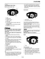
Push the “SELECT” button to switch the dis-
play between the odometer mode “ODO”, the
tripmeter modes “TRIP A” and “TRIP B” and
the stopwatch mode in the following order:
TRIP A
→
TRIP B
→
ODO
→
Stopwatch
→
TRIP A
If the fuel level warning light comes on, the
odometer display will automatically change to
the fuel reserve tripmeter mode “F-TRIP” and
start counting the distance traveled from that
point. In that case, push the “SELECT” button
to switch the display between the various trip-
meter, odometer, and stopwatch modes in the
following order:
F-TRIP
→
Stopwatch
→
TRIP A
→
TRIP B
→
ODO
→
F-TRIP
To reset a tripmeter, select it by pushing the
“SELECT” button, and then push the “RESET”
button for at least one second. If you do not
reset the fuel reserve tripmeter manually, it will
reset itself automatically and the display will
return to the prior mode after refueling and
traveling 5 km (3 mi).
Stopwatch mode
To change the display to the stopwatch mode,
select it by pushing the “SELECT” button. (The
stopwatch digits will start flashing.) Release
the “SELECT” button, and then push it again
for a few seconds until the stopwatch digits
stop flashing.
Standard measurement
1. Push the “RESET” button to start the stop-
watch.
2. Push the “SELECT” button to stop the stop-
watch.
3. Push the “SELECT” button again to reset
the stopwatch.
Split-time measurement
1. Push the “RESET” button to start the stop-
watch.
2. Push the “RESET” button or start switch
“
” to measure split-times.
(The colon “:” will start flashing.)
3. Push the “RESET” button or start switch
“
” to display the final split-time or push
the “SELECT” button to stop the stopwatch
and display total elapsed time.
4. Push the “SELECT” button to reset the
stopwatch.
TIP
To change the display back to the prior mode,
push the “SELECT” button for a few seconds
until the stopwatch digits flash.
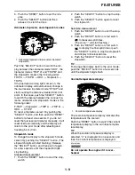
Coolant temperature display
The coolant temperature display indicates the
temperature of the coolant.
Push the “RESET” button to switch the coolant
temperature display to the air intake tempera-
ture display.
TIP
When the coolant temperature display is
selected, “C” is displayed for one second, and
then the coolant temperature is displayed.
ECA13S1002
Do not operate the engine if it is over-
heated.
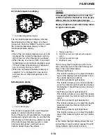
1. Odometer/tripmeters/fuel reserve tripmeter/
stopwatch
1. Coolant temperature display
Содержание R6 2009
Страница 1: ...SERVICE MANUAL YZFR6Y C 13S 28197 11 LIT 11616 22 51 2009 ...
Страница 6: ......
Страница 8: ......
Страница 60: ...LUBRICATION SYSTEM CHART AND DIAGRAMS 2 29 EAS20410 LUBRICATION DIAGRAMS 1 2 3 4 ...
Страница 62: ...LUBRICATION SYSTEM CHART AND DIAGRAMS 2 31 1 2 3 4 8 7 6 5 ...
Страница 64: ...LUBRICATION SYSTEM CHART AND DIAGRAMS 2 33 1 2 3 4 5 ...
Страница 65: ...LUBRICATION SYSTEM CHART AND DIAGRAMS 2 34 1 Oil cooler 2 Oil filter 3 Oil pipe 4 Oil pump 5 Oil strainer ...
Страница 66: ...LUBRICATION SYSTEM CHART AND DIAGRAMS 2 35 1 5 4 3 2 ...
Страница 68: ...LUBRICATION SYSTEM CHART AND DIAGRAMS 2 37 3 1 2 5 4 ...
Страница 70: ...LUBRICATION SYSTEM CHART AND DIAGRAMS 2 39 1 3 2 ...
Страница 71: ...LUBRICATION SYSTEM CHART AND DIAGRAMS 2 40 1 Oil pipe 2 Main axle 3 Drive axle ...
Страница 72: ...COOLING SYSTEM DIAGRAMS 2 41 EAS20420 COOLING SYSTEM DIAGRAMS 1 2 3 4 ...
Страница 73: ...COOLING SYSTEM DIAGRAMS 2 42 1 Radiator inlet hose 2 Radiator inlet pipe 3 Thermostat outlet hose 4 Radiator ...
Страница 74: ...COOLING SYSTEM DIAGRAMS 2 43 A A 2 1 3 4 5 6 7 8 6 13 8 9 15 14 9 10 11 12 ...
Страница 76: ...CABLE ROUTING 2 45 EAS20430 CABLE ROUTING ...
Страница 78: ...CABLE ROUTING 2 47 ...
Страница 80: ...CABLE ROUTING 2 49 ...
Страница 82: ...CABLE ROUTING 2 51 ...
Страница 84: ...CABLE ROUTING 2 53 ...
Страница 86: ...CABLE ROUTING 2 55 ...
Страница 88: ...CABLE ROUTING 2 57 ...
Страница 90: ...CABLE ROUTING 2 59 A A ...
Страница 92: ...CABLE ROUTING 2 61 ...
Страница 95: ......
Страница 135: ......
Страница 206: ...CHAIN DRIVE 4 71 1 2 3 a a New ...
Страница 209: ......
Страница 240: ...PICKUP ROTOR 5 31 ...
Страница 286: ...TRANSMISSION 5 77 ...
Страница 290: ...RADIATOR 6 3 b Apply 100 kPa 14 50 psi 1 0 kg cm2 of pressure c Measure the indicated pressure with the gauge ...
Страница 300: ...WATER PUMP 6 13 ...
Страница 316: ...AIR INDUCTION SYSTEM 7 15 EAS27040 AIR INDUCTION SYSTEM 2 1 2 4 3 4 3 6 4 5 A A ...
Страница 323: ......
Страница 324: ...IGNITION SYSTEM 8 1 EAS27090 IGNITION SYSTEM EAS27110 CIRCUIT DIAGRAM ...
Страница 330: ...ELECTRIC STARTING SYSTEM 8 7 EAS27160 ELECTRIC STARTING SYSTEM EAS27170 CIRCUIT DIAGRAM ...
Страница 336: ...CHARGING SYSTEM 8 13 EAS27200 CHARGING SYSTEM EAS27210 CIRCUIT DIAGRAM ...
Страница 337: ...CHARGING SYSTEM 8 14 1 AC magneto 2 Rectifier regulator 6 Main fuse 7 Battery 11 Engine ground ...
Страница 339: ...CHARGING SYSTEM 8 16 ...
Страница 340: ...LIGHTING SYSTEM 8 17 EAS27240 LIGHTING SYSTEM EAS27250 CIRCUIT DIAGRAM ...
Страница 344: ...SIGNALING SYSTEM 8 21 EAS27270 SIGNALING SYSTEM EAS27280 CIRCUIT DIAGRAM ...
Страница 351: ...SIGNALING SYSTEM 8 28 ...
Страница 352: ...COOLING SYSTEM 8 29 EAS27300 COOLING SYSTEM EAS27310 CIRCUIT DIAGRAM ...
Страница 355: ...COOLING SYSTEM 8 32 ...
Страница 356: ...FUEL INJECTION SYSTEM 8 33 EAS27330 FUEL INJECTION SYSTEM EAS27340 CIRCUIT DIAGRAM ...
Страница 395: ...FUEL INJECTION SYSTEM 8 72 ...
Страница 396: ...FUEL PUMP SYSTEM 8 73 EAS27550 FUEL PUMP SYSTEM EAS27560 CIRCUIT DIAGRAM ...
Страница 399: ...FUEL PUMP SYSTEM 8 76 ...
Страница 400: ...ELECTRICAL COMPONENTS 8 77 EAS27970 ELECTRICAL COMPONENTS ...
Страница 402: ...ELECTRICAL COMPONENTS 8 79 1 5 4 3 2 6 7 8 9 10 12 13 11 14 15 16 17 18 ...
Страница 404: ...ELECTRICAL COMPONENTS 8 81 EAS27980 CHECKING THE SWITCHES ...
Страница 431: ......
Страница 432: ...YAMAHA MOTOR CO LTD 2500 SHINGAI IWATA SHIZUOKA JAPAN ...

