background image

16

OPERATING INSTRUCTIONS (continued)
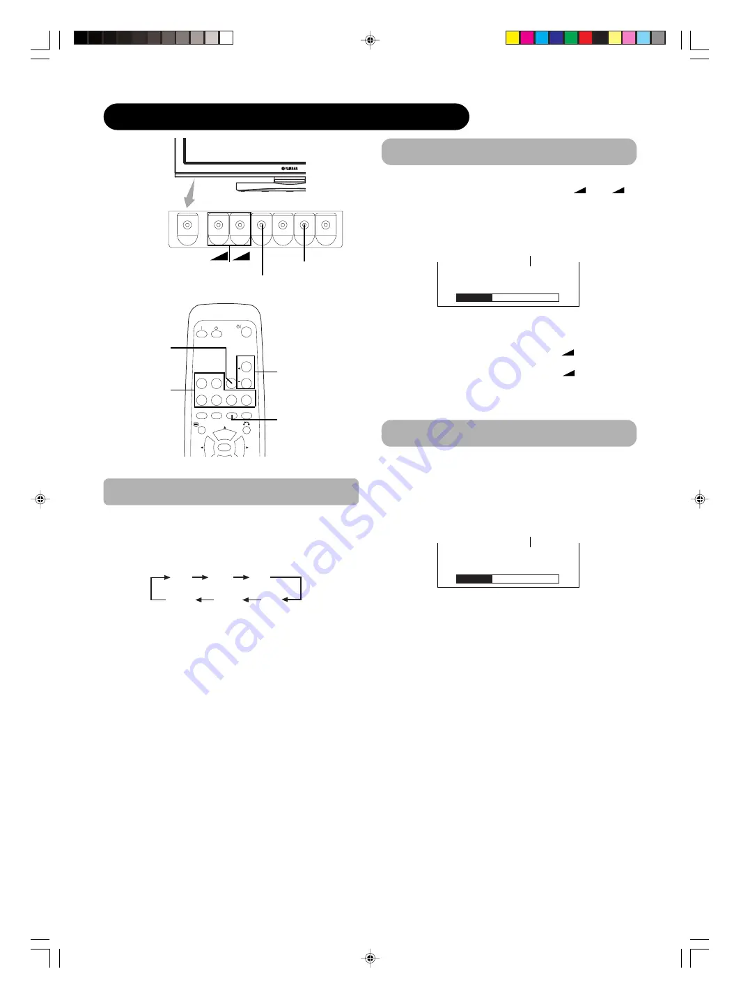
SIZE button

INPUT SELECT button

AV1

AV2

RGB 1

RGB 2

AV3

MUTE

VOL

AV4

AUTO

P

IN 

P

OK

SIZE

RECALL

    MENU

RGB/VIDEO

buttons

SIZE button

VOLUME
UP/DOWN buttons

MUTE button

Input Switching

 AV1         AV2         AV3

 RGB2         RGB1        AV4

• Input can be switched by pressing the AV1, AV2, AV3,

AV4, RGB1 or RGB2 buttons of the remote control.

• Input can be switched in the sequence of AV1 

 AV2 

AV3 

 AV4 

 RGB1 

 RGB2 by pressing the INPUT

SELECT button of the monitor.

Volume Adjustment

The volume can be adjusted by pressing the VOL+ and
VOL- buttons of the remote control (or the 


    and

volume buttons of the monitor unit).

• When a button is pressed, the volume adjustment

status guide will be displayed.

• The volume will increase when the VOL+ (or 


) button is

pressed while the guide is being displayed.

   •The volume will decrease when the VOL- (or 


   ) button is

pressed while the guide is being displayed.

Audio Mute

 Volume 15

Volume setting value

Adjustment status guide display

The audio volume can be temporarily muted by pressing
the MUTE button of the remote control.

• When a button is pressed, the volume adjustment

status guide (magenta) will be displayed.

   •The volume setting can be lowered by pressing the VOL- button

while the audio is mute.

   •The muting can be cancelled by pressing the VOL+ button or

MUTE button while the audio is mute.

When the MUTE button of the remote control is pressed
again, the audio will be restored and the volume display
(green) will appear.

 Volume 15

Volume setting value

Adjustment status guide display

(The display color will change to magenta.)

VOLUME
UP/DOWN
buttons

+

+

+

013_PDM-5520_U_E

12/13/04, 9:23 AM

16

Содержание PDM-5520

Страница 1: ......

Страница 2: ...no user serviceable parts inside the monitor Model and serial numbers are indicated on back side of the monitor CAUTION Adjust only those controls that are covered in the instructions as improper changes or modifications not expressly approved by YAMAHA could void the user s authority to operate the monitor POWER SOURCE THIS MONITOR IS DESIGNED TO OPERATE ON 120 VOLTS 60Hz ALTERNATING CURRENT INSE...

Страница 3: ...roduct damage and or personal injury 16 Follow instructions for wall shelf or ceiling mounting as recommended by the manufacturer 17 An outdoor antenna should not be located in the vicinity of overhead power lines or other electrical circuits 18 If an outside antenna is connected to the receiver be sure the antenna system is grounded so as to provide some protection against voltage surges and buil...

Страница 4: ...sted in FCC Regulations Part 15 for Class B digital devices Compliance with these requirements provides a reasonable level of assurance that your use of this product in a residential environment will not result in harmful interference with other electronic devices This equipment generates uses radio frequencies and if not installed and used according to the instructions found in theusers manual ma...

Страница 5: ...tion be sure to deliver this manual to the customer and explain to the customer how to handle the product Notes about This Manual The information in this manual is subject to change without notice While meticulous care has been taken in the preparation of this manual you are requested to notify your dealer or us should you have any comments views or questions about our product Fully understand the...

Страница 6: ...lt in Video Unit 1 A Composite S video terminal and two component terminals have been added A composite video output terminal is also provided as a monitoring output 2 A wide range of devices other than personal computers can also be connected 3 It is possible to swich the component terminal to RGB input from the Menu screen 4 A SCART terminal is also provided for the signal of the European standa...

Страница 7: ...ECIFICATIONS 24 Signal Input 25 Recommended Signal List 26 INSTALLATION INSTRUCTIONS FOR PC 27 Connecting to a PC 27 Power Cord Connection 28 OPERATING INSTRUCTIONS FOR PC 29 Turning Power On and Off 29 Input Switching 30 Volume Adjustment 30 Audio Mute 30 Size Switching 31 Input Signal Screen Display 31 Automatic Adjustment of Screen Position and the Clock 32 Independant Operation of Multiple Mon...

Страница 8: ...pped and or broken it could result in an injury and continued use could result in fire or electrical shock Do not place the monitor on an unstable slanted or vibranting surface such as a wobbly or inclined stand Do not obstruct the ventilation of the monitor If the ventilation is obstructed during the operation of the monitor or just after switching off the power it could result in damage and shor...

Страница 9: ...us and minus terminals are correctly aligned when loading the battery If you observe a leakage of the battery wipe out the liquid and then replace the battery If the liquid adheres your body or clothes rinse well with water Obey the local laws on disposing the battery Be careful in moving the monitor Neglect could result in an injury or damage Do not move the monitor during use Before moving disco...

Страница 10: ... antennas in order for the monitor not to receive interference The antenna cable of Radio should be kept away from the monitor Use a coaxial cable for antenna You can check if this monitor influences Radio receivers by turning off all other equipment other than the monitor If you find a problem receiving Radio when using the monitor check the instructions mentioned above Precautions for the cable ...

Страница 11: ...ndicapped people Disposal of this product may require specific instructions pertaining to your resident region Never guess or take any chances with electrical equipment of any kind it is better to be safe than sorry PRECAUTIONS Please read this User s Manual thoroughly especially the IMPORTANT SAFETY INSTRUCTIONS and the CAUTION READ THIS BEFORE OPERATING YOUR UNIT and the PRECAUTIONS sections Mis...

Страница 12: ... Main power switch 15 11 15 Menu button INPUT SELECT button OK button 16 RECALL button SELECT button SIZE button SELECT button 17 15 SUB POWER button VOLUME UP DOWN buttons ADJUST buttons 16 18 Caution when moving the main unit As this product is heavy whenever it is moved two or more people are required to transport it safely Whenever carrying this product hold it by the top and bottom on both en...

Страница 13: ...ndue force on the remote control To avoid possible failures Do not splash the remote control with water or put it on a wet object If you do not intend to use the remote control for an extended period of time remove the batteries from it If the remote control begins to lack responsiveness replace the batteries Strong light such as direct sunlight impinging on the photoreceptor of the remote control...

Страница 14: ...TION Use one of commercially available mount units to install this product A mount of insufficient strength or inadequate design can cause overturning or dropping and result in fire electrical shock or injury Please note that our company assumes absolutely no responsibility for personal injuries or property damage caused by improper installation Installation of the wall mount unit and ceiling moun...

Страница 15: ...ignal from AV1 AV2 AV3 or AV4 input that is displayed on the screen at the time If the adaptor included is applied to AV4 input as shown in the drawing it is impossible to receive RGB signal An example of connecting video imaging device DVI STB and RGB component setup To Subwoofer To component video equipment Please use connection cable suitable for the terminal form of video equipment Terminal Si...

Страница 16: ...ower cord to this monitor 2 Connect the power cord plug to the power outlet The type of plug is different from this drawing for some countries CAUTION Use only the power cord provided Do not use a power supply voltage other than that indicated AC100 240V 50 60Hz as this may cause fire or electric shock 012_PDM 5520_U_E 12 13 04 9 23 AM 14 ...

Страница 17: ...be Failures ATTENTION Avoid repeatedly turning the monitor on and off at short intervals Failures might result from such operation Turn off the main power switch if you do not plan to use the monitor for an extended period of time If a power failure occurs while the monitor is running it will be powered on upon recovery from the failure Turn off the unit main power switch before you leave the area...

Страница 18: ...ill increase when the VOL or button is pressed while the guide is being displayed The volume will decrease when the VOL or button is pressed while the guide is being displayed Audio Mute Volume 15 Volume setting value Adjustment status guide display The audio volume can be temporarily muted by pressing the MUTE button of the remote control When a button is pressed the volume adjustment status guid...

Страница 19: ...t to be viewed without picture distortion Each time the SIZE button of the remote control or the monitor is pressed the screen display size will change in sequence and the status will be displayed at the bottom of the screen During VIDEO signal input AV1 AV2 AV3 AV4 RGB1 set to DVI STB and RGB2 set to Component The size will be fixed Full mode and not change when receiving the component signal of ...

Страница 20: ... by pressing the and SELECT buttons the audio of the video will be output from the side on which the speaker icon is located The same video input mode cannot be selected for both screens at the same time Pressing the PINP button or the RETURN button will cancel the 2 pictures display When the Video input is set to RGB Video this Split mode is not possible Refer to the table for 2 pictures Split mo...

Страница 21: ...YNR Off Next Prev Select Return Picture Day YNR Off CNR Off Film Mode On PAL Comb Filter On LTI Off CTI Off Black Enhancement Off Auto Color Off Reset Reset Select Set Return OK Auto Color Off Next Prev On Off Return Picture Day Color Temp Adjust Color Management Color Decoding Select Set Return OK Picture Color Temp Adjust On Amplitude Red 63 Green 0 Blue 31 Cut Off Red 31 Green 0 Blue 31 Reset R...

Страница 22: ...ine picture detail and provide purer color Adjusts the sharpness of the picture signal Adjusts the sharpness of the color signal Adjusts the black level compensation This is available only when receiving an NTSC composite S Video signal This monitors and adjusts the color to maintain constant color levels It also maintains natural flesh tones while preserving fidelity of background colors Turn On ...

Страница 23: ...dned Darkenes red only Darkens green only Darkens colors Enhances red and weakens green Magenta is strengthened Red is strengthened Yellow is strengthened Green is strengthened Cyan is strengthened Blue is strengthened Lightens red only Lightens green only Lightens colors Enhances green and weakens red Magenta Red Yellow Green Cyan Blue Red Green Color Tint Off On RGB R G B FUNCTION MENU Picture A...

Страница 24: ... lot of noise or has a low level at Auto and the operation is erratic set this to match the input signal When the component signal is received this setting is not available grayed out This should correspond to the signal mode of the signal from the equipment that is connected to AV1 video input terminal Normally set this to Auto The signal mode of the input signal will be automatically recognized ...

Страница 25: ...DVI STB RGB Component Auto HDTV SDTV DVD Approximately 1 sec after adjustment is completed the adjustments will be recorded as shown in the table below Menu Picture Function Setup Display Yellow Green Cyan Blue Color Decoding Red Green Color Tint Video Power Save System Color System AV1 AV2 AV3 AV4 Video Input AV1 AV2 AV4 Audio Input AV1 AV2 AV3 AV4 RGB1 RGB2 Registration condition 1 setting is re...

Страница 26: ... RGB1 audio input terminal 3 5mm Stereo Mini Jack RGB2 analog RGB input terminal D sub 15 pin RGB2 audio input terminal 3 5mm Stereo Mini Jack 0 7 V 1 0 Vp p analog RGB Recommended Signal 480i 576i 480p 576p 1080i 50 1080i 60 720p 60 H V separate TTL level 2K H V composite TTL level 2K Sync on green 0 3 Vp p 75 47 modes AV1 composite video input terminal RCA AV1 Y PB PR video input terminal RCA AV...

Страница 27: ...ng the signals listed on the following page In this case use H V seperate sync or H V composite sync Sync signal type H V seperate sync H V composite sync sync on Green Priority 1 2 3 Pin 1 2 3 4 Frame Input signal Y Y GND C C GND GND S input connector pin specifications Scart connector pin specifications Pin 1 2 3 4 5 6 7 8 9 10 11 Signal AUDIO OUT RIGHT AUDIO IN RIGHT AUDIO OUT LEFT MONO AUDIO G...

Страница 28: ... 65 00 75 00 78 75 27 00 74 25 74 25 No 1 2 3 4 5 6 7 8 9 10 11 12 13 14 15 16 17 Signal Name VGA W VGA VESA 480p 720p 60 1080i 60 Remarks WVGA type On EIA 861 EIA 861 EIA 861 Signal Mode Recommended Signal List PRODUCT SPECIFICATIONS continued With Composite Input AV1 AV4 input and S video Input AV3 input Resolution 525 625 Vertical frequency Hz 59 94 50 00 Horizontal frequency kHz 15 73 15 63 Do...

Страница 29: ...erminal RGB 1 or RGB 2 on the rear panel of this monitor to the display signal output terminal of the personal computer Use a cable that fits the input terminal of this device and the output terminal of the personal computer Depending on the type of personal computer being connected the use of an optional conversion adapter or the adapter provided with the personal computer may be necessary in som...

Страница 30: ...e power cord to this monitor 2 Connect the power cord plug to the power outlet The type of plug is different from this drawing for some countries CAUTION Use only the power cord provided Do not use a power supply voltage other than that indicated AC100 240V 50 60Hz as this may cause fire or electric shock 014_PDM 5520_U_E 12 13 04 9 24 AM 28 ...

Страница 31: ... to be Failures ATTENTION Avoid repeatedly turning the monitor on and off at short intervals Failures might result from such operation Turn off the main power switch if you do not plan to use the monitor for an extended period of time If a power failure occurs while the monitor is running it will be powered on upon recovery from the failure Turn off the unit main power switch before you leave the ...

Страница 32: ...atus guide display The audio volume can be temporarily muted by pressing the MUTE button of the remote control When a button is pressed the volume adjustment status guide magenta will be displayed The volume setting can be lowered by pressing the VOL button while the audio is mute The muting can be cancelled by pressing the VOL button or MUTE button while the audio is mute When the MUTE button of ...

Страница 33: ...ay Resolution Display 640 X 480 VGA 800 X 600 SVGA 1024 X 768 XGA 1280 X 768 WXGA 1280 X 1024 SXGA 1600 X 1200 UXGA 1366 X 768 WXGA Full display Full Normal Real Zoom1 Zoom2 Zoom3 Circular display Processes such as compression thinning and expansion are performed for the above signal display Because of this there is a possibility that flicker may become noticeable on Zoom 1 3 depending on the disp...

Страница 34: ...endant Operation of Multiple Monitors ID No The remote control ID No can be checked by pressing the ID SET button while holding down the ID button Monitor ID No Remote control ID No When the MENU button is pressed the adjustment menu screen will be displayed from there PC signal adjustment and setting is possible by using the SELECT button ADJUST button and OK button Refer to concerning the adjust...

Страница 35: ... the gap between brightness and darkness Black is set off for increased overall brightness Lightens colors Enhances green and weakens red Brighter scenes are increased in reddish color Brighter scenes are increased in greenish color Brighter scenes are increased in bluish color Dark scenes are increased in reddish color Dark scenes are increased in greenish color Dark scenes are increased in bluis...

Страница 36: ...ise would not be heard Adjust it depending on the user s preference This features the spacious sound effects of a stadium This will automatically adjust volume so each channel and input has the same average volume level The original factory settings for the items of this Menu page can be restored by pressing the OK button Selected characters Audio Mode Treble Bass Balance SRS TruBass Matrix Surrou...

Страница 37: ...een Display every time the input mode and signal mode are changed Set to OFF if the Input Signal Screen Display is not needed when switching signals Assigns ID Nos to the monitors so that they can be controlled individually up to 7 monitors can be controlled This function changes each level of RGB signal invert to reduce the panel image retention When this function is required select On continuous...

Страница 38: ...utton This is effective only for RGB2 Normally set to 0 7 V If white is found to spread across the screen set to 1 0 V This is effective only for RGB2 Set this to Off if the frequency information of the Input Signal Screen Display is not required This is only available for W VGA signal When it is set to On the display area mode can be selected Full or Real This is only available for W XGA signal W...

Страница 39: ...gistered 1 setting is registered not registered For every signal Mode 1 setting is registered Only for RGB2 1 setting is registered 1 setting is registered Menu Picture Audio Display Contrast Brightness Color Tint Picture Enhancement Color temperature Color Temp Adjust R Amplitude G Amplitude B Amplitude R Cut Off G Cut Off B Cut Off Audio Mode Treble Bass Balance SRS TruBass Matrix Surround Perfe...

Страница 40: ...nel Action Recheck the personal computer power switch status and the connection status Recheck the input signal specifications RGB2 RGB H 48 4kHz V 60 1 Hz Min OFF No Sync Signal Invalid Scan Freq RGB 43 45 When the RGB1 RGB2 input is selected When this unit is connected to a VESA DPMS computer the Power Save Off mode can be set to be activated automatically when the computer is not being used to ...

Страница 41: ... reduce image retention Refer to Panel Life Extend 1 or Extend 2 shown on Set the plasma monitor to an Screen Wipe or Inverse display The occurrence of image retention when displaying images of identical patterns such as static images for long periods of time can be reduced by displaying a reversed color or completely white screen for about 1 2 hours after terminating the display Settings can be m...

Страница 42: ... is detected Check the way the signal cable is connected Make sure that the switch of the computer imaging equipment etc is turned on Make sure the computer is not in the power save mode Check to see if the input selection matches the connection terminal An input signal is not received normally Check to see if the input signal matches the monitor specifications Check the way the signal cable is co...

Страница 43: ... that this is not a malfunction High precision technology is used to manufacture the plasma display panel However in some cases there are minor defects in some parts of the screen Please note that this is not a malfunction The plasma display panel is lighting the phosphors by the discharge of internal radiation Depending on the screen contents in rare cases this may cause vertical stripes to appea...

Страница 44: ... Adjustment procedure Text displayed across the screen appears blurred in its entirety figure 2 A fine pattern flickers when displayed on the screen figure 3 Figure 2 Figure 3 1 Press the AUTO button on the remote control When adjustment is not possible with Auto Adjust 2 Press the MENU button The Main Menu will be displayed 3 Press the SELECT button and select Setup 4 Press the OK button The Setu...

Страница 45: ...rox 55 inches 1229 H x 691 V mm diagonal 1410mm 1366 H x 768 V pixels 1394 W x 857 H x 105 D mm 63 5kg Operating 5 C to 35 C Storage 0 C to 40 C Operating 20 to 80 Storage 20 to 90 non condensing AC100 240V 50 60Hz 530W 3W 12W 12W 6 sub woofer RCA RGB1 DVI input terminal DVI D RGB1 audio input terminal 3 5mm Stereo Mini Jack RGB2 analog RGB input terminal D sub 15 pin RGB2 audio input terminal 3 5...

Страница 46: ...put RGB1 input Make sure that the signal of the equipment to be connected is compatible with the specifications on this list Resolution 640 X 400 640 X 480 864 X 480 640 X 480 640 X 480 640 X 480 800 X 600 800 X 600 800 X 600 800 X 600 800 X 600 1024 X 768 1024 X 768 1024 X 768 Vertical frequency Hz 70 08 59 94 59 94 72 81 75 00 85 01 56 25 60 32 72 19 75 00 85 06 60 00 70 07 75 03 Horizontal freq...

Страница 47: ...14 15 16 17 18 19 20 21 22 23 24 25 26 27 28 29 30 Signal Name VGA W VGA VESA Macintosh W XGA W XGA Resolution 640 X 400 640 X 480 864 X 480 640 X 480 640 X 480 640 X 480 800 X 600 800 X 600 800 X 600 800 X 600 800 X 600 1024 X 768 1024 X 768 1024 X 768 1024 X 768 1152 x 864 1280 x 1024 1280 x 1024 1280 x 1024 1600 x 1200 1600 x 1200 1600 x 1200 640 x 480 832 x 624 1024 x 768 1152 x 870 1280 x 768...

Страница 48: ......

Страница 49: ... 6Ω12W スピーカー端子 6Ω12W PDM 5520 Monitor rear panel U S To AC outlet PHONO DVR STANDBY ON PURE DIRECT 2CH MULTI CH SPEAKERS VIDEO AUX REC OUT ZONE 2 INPUT MODE SOURCE REMOTE DVD DTV LD MD TAPE CD R TUNER CD VIDEO AUX VCR 2 VCR 1 SAT CABLE A B STRAIGHT EFFECT MULTI CH INPUT DSP PROGRAM BALANCE TONE CONTROL VOLUME INPUT SELECTOR MULTI JOG SILENT OPTIMIZER MIC PHONES OPTICAL R AUDIO L VIDEO S VIDEO TUNI...

Страница 50: ...ess levels as much as possible Français Rétention d image La rétention peut être un problème pour les écrans Plasma néanmoins si vous suivez les simples instructions suivantes vous pourrez profiter de votre écrans pendant de longues années YAMAHA a pourvu ses écrans moniteurs plasma de fonctions permettant de réduire la rétention d image Veuillez s il vous plaît vérifier dans le mode d emploi de c...

Отзывы: