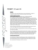
background image

8-38

E

HULL

HOOD

DECK AND HULL

DECK AND HULL

EXPLODED DIAGRAM

REMOVAL AND INSTALLATION CHART

Step

Procedure/Part name

Q’ty

Service points

DECK AND HULL DISASSEMBLY

Follow the left “Step” for disassembly.

1

Bolt

2

2

Bow eye

1

3

Nut

2

4

Rope hole fitting

2

5

Nut

1

6

Spout

1

7

Bolt

6

8

Sponson

2

NOTE:

Install the starboard and port side sponsons
at the same position.

Содержание GP1300R WaveRunner 2003

Страница 1: ...SERVICE MANUAL GP1300R WaveRunner F1G 28197 1F 11 LIT 18616 02 44 LIT186160244 ...

Страница 2: ...Yamaha has a policy of continuously improving its products models may differ in detail from the descriptions and illustrations given in this publication Use only the latest edition of this manual Authorized Yamaha dealers are notified periodically of modifications and significant changes in specifications and procedures and these are incorporated in successive editions of this manual A10001 0 Wave...

Страница 3: ...evised format the condition of a faulty component will precede an arrow symbol and the course of action required will follow the symbol e g Bearings Pitting scratches Replace To assist you in finding your way through this manual the section title and major heading is given at the top of every page ILLUSTRATIONS The illustrations within this service manual represent all of the designated models CRO...

Страница 4: ...low WARNING instructions could result in severe injury or death to the machine operator passenger s a bystander or a person inspecting or repairing the watercraft CAUTION A CAUTION indicates special precautions that must be taken to avoid damage to the water craft NOTE A NOTE provides key information to make procedures easier or clearer IMPORTANT This part has been subjected to change of specifica...

Страница 5: ...dicate parts to be lubricated or replaced see SYMBOLS 4 A job instruction chart accompanies the exploded diagram providing the order of jobs names of parts notes in jobs etc 5 Dimension figures and the number of parts are provided for fasteners that require a tightening torque Example Bolt or screw size M10 D 25 mm L 6 Jobs requiring more information such as special service tools and technical dat...

Страница 6: ...t Symbols F to H in an exploded diagram indi cate the grade of lubricant and the lubrication point F Apply Yamaha 2 stroke motor oil G Apply water resistant grease Yamaha grease A Yamaha marine grease H Apply molybdenum disulfide grease Symbols I to N in an exploded diagram indi cate the type of sealant or locking agent and the application point I Apply Gasket Maker J Apply Yamabond No 4 K Apply L...

Страница 7: ...1 GEN INFO SPECIFICATIONS 2 SPEC PERIODIC INSPECTION AND ADJUSTMENT 3 INSP ADJ FUEL SYSTEM 4 FUEL POWER UNIT 5 POWR JET PUMP UNIT 6 JET PUMP ELECTRICAL SYSTEM 7 ELEC HULL AND HOOD 8 HULL HOOD TROUBLE ANALYSIS 9 TRBL ANLS A30000 0 ...

Страница 8: ...ER 1 1 JET PUMP UNIT SERIAL NUMBER 1 1 HULL IDENTIFICATION NUMBER H l N 1 1 SAFETY WHILE WORKING 1 2 FIRE PREVENTION 1 2 VENTILATION 1 2 SELF PROTECTION 1 2 PARTS LUBRICANTS AND SEALANTS 1 2 GOOD WORKING PRACTICES 1 3 DISASSEMBLY AND ASSEMBLY 1 4 SPECIAL SERVICE TOOLS 1 5 MEASURING AND DIAGNOSIS 1 5 REMOVAL AND INSTALLATION 1 7 ...

Страница 9: ... D number F1G 800301 1 ENGINE SERIAL NUMBER The engine serial number is stamped on a label 1 attached to the engine unit Starting serial number 60T 1000001 JET PUMP UNIT SERIAL NUMBER The jet pump unit serial number is stamped on a label attached to the intermediate housing HULL IDENTIFICATION NUMBER H l N The H l N is stamped on a plate 1 attached to the hull on the aft starboard right side ...

Страница 10: ...tities they may cause loss of con sciousness and death within a short time When test running an engine indoors e g in a water tank be sure to do so where adequate ventilation can be maintained SELF PROTECTION Protect your eyes by wearing safety glasses or safety goggles during all operation involving drilling and grinding or when using an air com pressor Protect your hands and feet by wearing prot...

Страница 11: ...part of the body thoroughly with soap and hot water after contact with a lubricant or lubricant soiled clothing has been made 5 To protect your skin apply a protective cream to your hands before working on the watercraft 6 Keep a supply of clean lint free cloths for wiping up spills etc GOOD WORKING PRACTICES 1 The right tools Use the recommended special service tools to protect parts from damage ...

Страница 12: ...t during disassembly 2 Apply engine oil to the contact surfaces of moving parts during assembly 3 Install bearings with the manufacture iden tification mark in the direction indication in the installation procedure In addition be sure to lubricate the bearings liberally 4 Apply a thin coat of water resistant grease to the lip and periphery of an oil seal before installation 5 Check that moving par...

Страница 13: ...the special ser vice tools starting with part number 90890 MEASURING AND DIAGNOSIS 1 Digital multimeter YU 34899 A 2 Digital circuit tester 90890 03174 3 Dial gauge YU 03097 90890 01252 4 Pocket tester YU 03112 90890 03112 5 Fuel pressure gauge adapter YW 06842 90890 06842 6 Fuel pressure gauge YB 06766 90890 06786 7 Cylinder gauge set YU 03017 90890 06759 8 Compression gauge YU 33223 1 90890 0316...

Страница 14: ...869 E Test harness 6 pins YB 06848 Test harness FSW 6A 6 pins 90890 06848 F Test harness 6 pins YB 06849 Test harness SM6195021 6 6 pins 90890 06849 G Lower unit pressure vacuum tester YB 35956 A Vacuum pressure pump gauge set 90890 06756 H Yamaha diagnostic system CD ROM only 60V WS853 01 G YB 35956 A 90890 06756 9 0 YU 39991 90890 03172 A B YM 34487 90890 06754 C D YB 06870 90890 06870 YB 06869 ...

Страница 15: ... 8 Bearing puller assembly jet pump bearing 90890 06535 9 Stopper guide stand jet pump bearing 90890 06538 0 Driver rod L3 jet pump bearing 90890 06652 A Bearing housing needle bearing remover jet pump bearing YB 06112 Drive shaft needle bearing installer and remover jet pump oil seal YB 06196 B Needle bearing attachment jet pump bearing and oil seal 90890 06614 90890 06653 1 YW 06551 YW 06550 2 3...

Страница 16: ...ediate shaft and jet pump 90890 06606 G Drive shaft needle bearing depth stop jet pump bearing YB 34474 H Shaft holder intermediate shaft YB 06552 Crankshaft holder 20 intermediate shaft 90890 06552 I Drive shaft taper roller bearing cup installer intermediate shaft YB 06156 Bearing outer race attachment intermediate shaft 90890 06626 C YB 06085 90890 06634 D E YB 06071 90890 06606 F G YB 34474 YB...

Страница 17: ...ER 2 SPECIFICATIONS GENERAL SPECIFICATIONS 2 1 MAINTENANCE SPECIFICATIONS 2 3 ENGINE 2 3 JET PUMP UNIT 2 4 HULL AND HOOD 2 5 ELECTRICAL 2 5 TIGHTENING TORQUES 2 8 SPECIFIED TORQUES 2 8 GENERAL TORQUE 2 14 CABLE AND HOSE ROUTING 2 15 ...

Страница 18: ... h 63 0 16 6 13 9 Cruising range h 0 95 Engine Engine type 2 stroke Number of cylinders 3 Displacement cm3 cu in 1 297 79 1 Bore stroke mm in 84 78 3 31 3 07 Compression ratio 1 2 5 9 1 3 5 7 1 Intake system Reed valve Scavenging system Loop charge Exhaust system Wet exhaust YPVS Lubrication system Variable oil injection Cooling system Water cooled Starting system Electric starter Ignition system ...

Страница 19: ...mp Jet pump type Axial flow single stage Impeller rotation Counterclockwise viewed from rear Transmission Direct drive from engine Jet thrust nozzle horizontal angle Degree 23 23 Jet thrust nozzle trim angle Degree 5 0 5 10 15 Trim system Manual 5 positions Reverse system NA Fuel and oil Fuel Regular unleaded gasoline Minimum fuel rating PON 1 86 RON 2 90 Oil YAMALUBE 2 W 3 Fuel oil ratio wide ope...

Страница 20: ...0041 Wear limit mm in 0 155 0 0061 Piston pin boss inside diameter mm in 22 008 22 020 0 8665 0 8669 Piston rings Top Type Keystone Dimension B mm in 1 47 1 49 0 058 0 059 Dimension T mm in 3 0 3 2 0 118 0 126 End gap mm in 0 45 0 60 0 018 0 024 Ring groove clearance mm in 0 020 0 070 0 0008 0 0028 2nd Type Keystone Dimension B mm in 1 47 1 49 0 058 0 059 Dimension T mm in 3 0 3 2 0 118 0 126 End ...

Страница 21: ...kness mm in 0 6 0 024 Reed valve stopper height mm in 10 5 10 9 0 413 0 429 Reed valve warpage limit mm in 1 5 0 059 Fuel pump Pump type Electrical Output pressure kPa kgf cm2 psi 320 8 327 2 3 21 3 27 45 62 46 53 Coupling clearance Vertical mm in 0 0 5 0 0 020 Horizontal mm in 2 4 0 079 0 157 Item Unit Model GP1300R Jet pump Impeller material Stainless steel Number of impeller blades 4 Impeller p...

Страница 22: ...inder 3 Output peak voltage lower limit at cranking V 0 8 at 2 000 r min V 174 at 3 500 r min V 156 Stator Pickup coil W R W B W Y B Output peak voltage at cranking 1 V 6 0 at cranking 2 V 6 0 at 2 000 r min V 24 at 3 500 r min V 40 Pickup coil resistance 1 W R B Ω 459 561 Pickup coil resistance 2 W B B Ω 459 561 Pickup coil resistance 3 W Y B Ω 459 561 Lighting coil G G Output peak voltage at cra...

Страница 23: ...2 5 0 49 Wear limit mm in 6 5 0 26 Commutator undercut mm in 0 7 0 03 Limit mm in 0 2 0 01 Commutator diameter mm in 28 0 1 10 Limit mm in 27 0 1 06 Starter relay Rating Seconds 30 Engine temperature sensor Engine temperature sensor resistance B Y B Y at 20 C 68 F kΩ 54 2 69 0 at 100 C 212 F kΩ 3 12 3 48 Intake air temperature sensor Intake air temperature sensor resistance at 0 C 32 F kΩ 5 4 6 6 ...

Страница 24: ...2 F Ω 104 153 Speed sensor Output voltage on pulse V 11 6 Output pulse one full turn 2 Throttle position sensor Output voltage P B O at trolling speed V 0 793 0 807 Fuel sender Fuel sender resistance Position A Ω 133 5 136 5 Position B Ω 5 7 Fuel injector Fuel injector resistance 1 Ω 13 8 Oil level sensor Oil level sensor resistance Position A Ω 292 308 Position B Ω 97 103 Position C Ω 0 3 Fuse Ra...

Страница 25: ... Throttle cable locknut and adjuster throttle bodies end 1 11 1 1 8 0 Intake air temperature sensor intake silencer case cover 1 7 5 0 75 5 4 572 LT Intake silencer case cover intake silencer case Tapping screw ø6 13 1 8 0 18 1 3 Flame arrester intake silencer case Screw M5 6 0 8 0 08 0 6 Fuel rail throttle bodies Bolt M6 3 8 8 0 88 6 4 Oil pump cable oil pump lever 1st Bolt M5 1 2 2 0 22 1 6 572 ...

Страница 26: ...Engine unit engine mount Bolt M8 4 17 1 7 12 572 LT Exhaust manifold cylinder 1st Bolt M10 10 22 2 2 16 271 LT 2nd 39 3 9 28 1st Nut M10 2 22 2 2 16 2nd 39 3 9 28 Cooling water joint exhaust manifold Bolt M6 6 12 1 2 8 7 242 LT Throttle bodies bracket 1 2 throttle bodies joint balance plate plate reed valve assembly crankcase 1st Bolt M6 4 3 8 0 38 2 7 572 LT 2nd 7 6 0 76 5 5 Throttle bodies joint...

Страница 27: ...ver Bolt M6 3 14 1 4 10 242 LT Drive coupling crankshaft assembly Drive coupling 1 36 3 6 25 572 LT Flywheel magneto crankshaft assembly Bolt M10 1 74 7 4 53 E Starter motor negative battery lead crankcase 1st Bolt M8 1 9 0 0 9 6 5 A 2nd 18 1 8 13 Starter motor crankcase 1st Bolt M8 1 9 0 0 9 6 5 2nd 18 1 8 13 Mount bracket lower crankcase 1st Bolt M8 6 15 1 5 11 271 LT 2nd 27 2 7 19 Upper crankca...

Страница 28: ...lebar holder lower handlebar holder steering column Bolt M8 4 16 1 6 11 QSTS converter hull Nut M6 2 5 4 0 54 3 9 QSTS cable 1 2 locknut 2 16 1 6 11 Throttle lever assembly handlebar Screw M5 2 3 4 0 34 2 5 Handlebar switch assembly handlebar Screw M5 2 3 4 0 34 2 5 QSTS grip assembly handlebar Screw M6 1 3 4 0 34 2 5 Grip end handlebar Bolt M5 2 1 2 0 12 0 9 QSTS cable housing cover Screw M4 1 1 ...

Страница 29: ...64 4 6 Hood lock assembly deck Nut M6 2 6 4 0 64 4 6 Seat lock assembly seat Bolt M6 2 6 4 0 64 4 6 572 LT Bracket deck projection Nut M10 1 26 2 6 19 Bracket deck handgrip Bolt M8 2 5 2 0 52 3 8 Handgrip deck Nut M8 2 5 2 0 52 3 8 Seat bracket deck Nut M8 2 15 1 5 11 Battery box stay holder Nut M6 2 8 9 0 89 6 4 Battery box deck bracket Nut M8 2 13 1 3 9 4 Battery box electrical box Bolt M8 1 13 ...

Страница 30: ...ox Tapping screw ø6 6 3 9 0 39 2 8 Fuse holder stay electrical box Tapping screw ø6 1 3 4 0 34 2 5 Main and fuel pump relay electrical box Tapping screw ø6 1 3 9 0 39 2 8 Ground leads electrical box Bolt M6 2 7 6 0 76 5 5 ECM hull Nut 2 5 4 0 54 3 9 Slant detection switch hull Nut 2 5 4 0 54 3 9 Nut spring washer washer starter motor lead terminal starter motor Nut 1 8 8 0 88 6 4 Starter motor rea...

Страница 31: ...s of this manual To avoid warpage tighten multi fastener assemblies in a crisscross fashion and progressive stages until the specified tightening torque is reached Unless otherwise specified tightening torque specifications require clean dry threads Components should be at room temperature Nut A Bolt B General torque specifications N m kgf m ft lb 8 mm M5 5 0 0 5 3 6 10 mm M6 8 0 0 8 5 8 12 mm M8 ...

Страница 32: ...water pilot outlet 3 YPVS servomotor 4 Throttle cable 5 QSTS cable 6 Steering cable 7 Speed sensor lead 8 Positive battery lead 9 Cooling water temperature sensor lead 0 Exhaust temperature sensor lead A Negative battery lead B Starter motor lead C YPVS cables D Atmospheric pressure sensor E Water separator F Cooling water pilot outlet hose G Cooling water outlet hose H Wire harness I Electrical b...

Страница 33: ...D F F 1 F G F F M M C E E J J G G B C A J J L 5 7 H 2 K F J H 7 7 H C A B 7 H I 1 1 D C B A 0 9 8 7 6 5 4 3 2 1 È É Ê Ë Ì Í Ì Î L E È Align the parting line on the fuel filler neck with the lot mark on the fuel filler hose É To wire harness Ê To ventilation socket Ë To fuel tank Ì Down Í Up Î Bow ...

Страница 34: ...lectrical bilge pump lead 8 Steering cable 9 QSTS cable 0 Speed sensor lead A Negative battery lead B Starter motor lead C Speed sensor coupler D Oil level sensor coupler E Buzzer coupler F Engine stop switch coupler G Multifunction meter coupler H Start switch coupler I ECM coupler J Slant detection switch K Fuel pump coupler L Atmospheric pressure sensor coupler M Steering switch coupler N Wire ...

Страница 35: ... M L A N O 8 C D E B B F F B B C F F E D A 1 2 3 4 5 6 7 8 9 0 A B 7 A 5 P B 7 P Î Í È É Ê ÌË È To cylinder 3 É To cylinder 2 Ê To cylinder 1 Ë Cooling water temperature sensor Ì Exhaust temperature sensor Í To positive battery terminal Î To starter motor ...

Страница 36: ...7 1 È A 1 Bilge hose 1 2 Bilge hose 2 3 Steering cable 4 Bilge hose 3 5 QSTS cable 6 Bilge hose 4 7 Cooling water hose cooling water inlet 8 Flushing hose 9 Speed sensor lead 0 Cooling water hose cooling water outlet A Electrical bilge pump lead È Contact the corrugated tube bilge hose 1 to the hose screw clamp ...

Страница 37: ...of the rib on the fuel rail É Fasten oil delivery hoses 2 and 3 and the engine temperature sensor lead with a plastic tie Ê Fasten the sub wire harness with the plastic tie on the rib of the fuel rail Be sure to position the plastic tie so that the fastener is visible from the outside Ë Pass the oil bleed hose on the inside of the oil pump cable Ì To ECM Í Pass the oil return hose on the outside o...

Страница 38: ...ump and then tape it Ï To oil tank Ð To check valve Ñ Install the oil hoses into the hose holders so that the holders do not cover the check valve clips Ò Pass the intake air temperature sensor lead over the fuel hose Ó Pass the bleed hose under the exhaust cham ber bracket Be sure to install the L shaped bleed hose toward the oil pump ...

Страница 39: ...rt side Ê When fastening the corrugated tube of the fuel hose to the intake silencer slide it toward the fuel pump and then tighten it with a plastic tie Ë To cooling water pilot outlet on starboard side Ì To electrical box Í Install the exhaust joint so that it contacts the stoppers on the muffler assembly Î Face the red mark end of the cooling hose toward the cylinder head cover and then install...

Страница 40: ...YPVS servomotor fasten the throttle cable Ó Fasten the exhaust temperature sensor lead Ô To cylinder 1 Õ To cylinder 2 Ö To cylinder 3 Cooling water inlet Ø Install the white tape end of the negative battery lead to the battery Ù Fasten the sub wire harness and wire harness generator Ú Fasten the wire harness generator Û Route the sub wire harness under the cooling water hose Ü Install the oil pum...

Страница 41: ...ment 3 4 Trolling speed check 3 5 FUEL SYSTEM 3 7 Fuel line inspection 3 7 Water separator inspection 3 7 OIL INJECTION SYSTEM 3 8 Oil line inspection 3 8 POWER UNIT 3 9 Spark plug inspection 3 9 YPVS cable adjustment 3 10 ELECTRICAL 3 12 Battery inspection 3 12 JET PUMP UNIT 3 15 Impeller inspection 3 15 Water inlet strainer inspection 3 15 BILGE PUMP 3 16 Bilge strainer inspection 3 16 Electric ...

Страница 42: ...s 12 months 12 months 24 months Spark plug Inspect clean adjust 3 9 Lubrication points Lubricate 3 17 Intermediate housing Lubricate 1 2 2 3 19 Fuel system Inspect 3 7 Fuel tank Clean 3 7 Oil injection system Inspect clean 3 8 Throttle shaft Inspect Cooling water passages Flush 3 Water inlet strainer Inspect clean 3 15 Bilge strainer Clean 3 16 Electric bilge pump strainer Inspect clean 3 16 Impel...

Страница 43: ...nce Adjust 2 Adjust Steering cable joint steering column end Difference of distances a and b Maximum 5 mm 0 2 in Measurement steps Set the control grip to the neutral position Turn the handlebar lock to lock Measure distances a and b If the difference of distances a and b is not within specification adjust the cable joint Adjustment steps Set the control grip to the neutral position Loosen the loc...

Страница 44: ...d then tighten the locknut T R Locknut 6 8 N m 0 68 kgf m 4 9 ft lb Throttle cable inspection and adjustment 1 Measure Throttle lever free play a Out of specification Adjust 2 Adjust Throttle lever free play WARNING After adjusting the free play turn the han dlebar to the right and left and make sure that the trolling speed does not increase Throttle lever free play 4 7 mm 0 16 0 28 in Adjustment ...

Страница 45: ...le joint 2 Adjust QSTS cable Adjustment steps Set the control grip to the neutral posi tion Loosen the locknut 1 Remove the nut 2 and pivot pin 3 Set the jet thrust nozzle in the center position Turn the cable joint 4 in or out to adjust lengths a and b Turn in Length b is increased Turn out Length a is increased WARNING The cable joint must be screwed in a minimum of 8 mm 0 31 in Connect the cabl...

Страница 46: ... of specification Proceed to step 2 2 If the trolling speed is out of specification check the following If no malfunctions are found after perform ing all of the checks replace the throttle bodies Check the spark plugs Refer to Spark plug inspection Check the throttle cable and oil pump cable Refer to Throttle cable inspection and adjustment Refer to OIL PUMP in Chapter 4 Check the intake passages...

Страница 47: ...ater accumulation the fuel lines for clogs or kinks and the fuel injectors for clogs Refer to FUEL SYSTEM Refer to FUEL TANK AND FUEL PUMP MODULE in Chapter 4 Refer to FUEL INJECTION SYSTEM in Chapter 4 Measure the compression pressure Refer to COMPRESSION PRESSURE MEASUREMENT in Chapter 5 Check the jet pump and impeller Refer to JET PUMP UNIT in Chapter 6 Check the diagnostic codes in the Diag no...

Страница 48: ...or Cracks damage Replace the quick connector Fuel pipe Cracks damage Replace the fuel pump Refer to FUEL INJECTION SYSTEM in Chapter 4 Fuel filler hose Fuel filler cap Cracks damage Replace 2 Check Fuel tank Cracks damage Replace Water accumulation Remove NOTE To remove water from the fuel tank remove the cap 1 and use a siphon pump T R Fuel tank cap screw clamp 1 3 N m 0 13 kgf m 0 9 ft lb Water ...

Страница 49: ...ubber seal Cracks wear Replace Oil hoses Oil tank Oil filler cap Cracks damage Replace Check valve Malfunction Replace CAUTION Do not allow the oil tank to become com pletely empty If the oil tank becomes empty the oil injection pump must be bled to ensure proper oil flow otherwise engine damage may occur Refer to OIL PUMP in Chapter 4 ...

Страница 50: ...ine 2 Clean Spark plug using a spark plug cleaner or wire brush Color guide Medium to light tan color Normal Whitish color Lean air fuel mixture Air leakage Incorrect settings Blackish color Overly rich air fuel mixture Electrical malfunction Excessive oil use Defective spark plug 3 Measure Spark plug gap a Out of specification Regap Spark plug gap 1 0 1 1 mm 0 039 0 043 in ...

Страница 51: ...to 1 2 of a turn b T R Spark plug 25 N m 2 5 kgf m 18 ft lb YPVS cable adjustment 1 Check YPVS valve position Incorrect position Adjust YPVS cables 1 and 2 Checking steps Start the engine and then turn it off NOTE Immediately after the engine stop switch is pushed the YPVS valves extend and retract two times to clean the exhaust ports If the engine is stopped without the engine stop switch being p...

Страница 52: ...ley with the hole in the cylinder Insert a 4 mm 0 16 in diameter pin through the pulley and cylinder holes Turn adjusters 3 and 4 in or out until the specified slack is obtained Turn in Slack is increased Turn out Slack is decreased Finger tighten locknuts 1 and 2 Remove the pin Start the engine and then turn it off Check the alignment of the holes If the holes are aligned correctly tighten the lo...

Страница 53: ...produce explosive gases Keep sparks flame cigarettes etc well away If using or charging the battery in an enclosed space make sure that it is well ventilated Always shield your eyes when working near batteries KEEP OUT OF THE REACH OF CHIL DREN Be sure to connect the breather hose to the battery Fire or explosion could result if the breather hose is damaged obstructed or not connected properly CAU...

Страница 54: ... service the impeller etc 2 Check Electrolyte level Low Add distilled water The electrolyte level should be between the maximum a and minimum b level marks CAUTION Use only distilled water Other types of water contain minerals which are harmful to batteries Filling steps Remove the filler caps Add distilled water to the maximum level mark Allow the battery to stand for 20 minutes If the electrolyt...

Страница 55: ...y 5 Install Battery breather hose 1 Battery Positive battery lead 2 Negative battery lead 3 with terminal extension at negative battery terminal Battery bands CAUTION Connect the positive lead to the battery terminal first Make sure that the battery leads are con nected properly Reversing the leads can seriously damage the electrical system Make sure that the battery breather hose is properly conn...

Страница 56: ...e the clearance at each impeller blade as shown a total of four measure ments Install the intake duct and intake grate Refer to JET PUMP UNIT in Chapter 6 Connect the battery leads a 1 Water inlet strainer inspection 1 Check Water inlet strainer Contaminants Clean Cracks damage Replace Checking steps Remove the ride plate Refer to JET PUMP UNIT in Chapter 6 Remove the water inlet cover 1 Check the...

Страница 57: ...bilge strainer and bilge strainer case Install the bilge strainer case 1 Electric bilge pump strainer inspection 1 Check Cap Strainer Contaminants Clean Checking steps Remove the battery box Refer to BATTERY BOX in Chapter 8 Remove the band 1 Remove the cap 2 and strainer 3 Check the cap and strainer Install the strainer and cap Install the band Install the battery box Refer to BATTERY BOX in Chap...

Страница 58: ...efore lubricating the throttle cable squeeze the throttle lever and remove the rubber seal 1 Recommended lubricant Rust inhibitor 2 Lubricate QSTS control cables handlebar end NOTE Before lubricating the QSTS control cables remove the QSTS cable housing cover Spray the rust inhibitor into the outer cables and apply grease to the inner cables Recommended lubricant Yamaha marine grease Yamaha grease...

Страница 59: ...vot shaft Steering cable jet thrust nozzle end QSTS cable jet thrust nozzle end Recommended grease Yamaha marine grease Yamaha grease A water resistant grease 5 Lubricate Steering cable Steering cable joint NOTE Disconnect the steering cable joint and then apply a small amount of grease to it Recommended grease Yamaha marine grease Yamaha grease A water resistant grease ...

Страница 60: ...te housing NOTE Using a grease gun fill the intermediate hous ing with the recommended grease through the grease nipples Recommended grease Yamaha marine grease Yamaha grease A water resistant grease Grease quantity 33 0 35 0 cm3 1 11 1 18 oz ...

Страница 61: ...nspection 4 8 Fuel pump module installation 4 8 Fuel hose connection 4 8 INTAKE DUCT AND INTAKE SILENCER 4 9 EXPLODED DIAGRAM 4 9 REMOVAL AND INSTALLATION CHART 4 9 SERVICE POINTS 4 11 Intake silencer installation 4 11 FUEL INJECTION SYSTEM 4 12 EXPLODED DIAGRAM 4 12 REMOVAL AND INSTALLATION CHART 4 12 SERVICE POINTS 4 18 Hose clamp removal 4 18 Hose clamp installation 4 18 Fuel hose disconnection...

Страница 62: ... PUMP 4 24 EXPLODED DIAGRAM 4 24 REMOVAL AND INSTALLATION CHART 4 24 SERVICE POINTS 4 27 Oil pump inspection 4 27 Oil hose inspection 4 27 Check valve inspection 4 27 Oil pump lever position adjustment 4 28 Oil pump bleeding 4 29 ...

Страница 63: ...OVAL Follow the left Step for removal Engine unit Refer to ENGINE UNIT in Chapter 5 Steering console cover assembly Refer to STEERING CONSOLE COVER in Chapter 8 1 Oil level sensor coupler 1 2 Plastic tie 1 Disconnect the oil filler hose from the oil filler neck 3 Nut 1 4 Oil filler neck 1 5 Rubber seal 1 Not reusable OIL TANK ...

Страница 64: ...ED DIAGRAM Step Procedure Part name Q ty Service points 6 Breather hose 1 7 Oil hose 1 8 Bolt 2 9 Strap 2 10 Oil tank 1 11 Hose screw clamp 1 12 Oil filler hose 1 13 Oil level sensor 1 Reverse the removal steps for installation ...

Страница 65: ...r Contaminants Clean Frays tears Replace Rubber seal Cracks wear Replace Oil hoses Oil filler cap Cracks damage Replace Check valve Faulty Replace Oil level sensor inspection Refer to INDICATION SYSTEM in Chapter 7 Oil tank inspection 1 Check Oil tank Cracks damage Replace ...

Страница 66: ...er hose 1 2 Check valve 1 3 Fuel tank breather hose 1 4 Fuel sender coupler 1 NOTE Make sure that the inner seal of the coupler is installed properly before connecting the coupler 5 Fuel pump module coupler 1 1 3 N m 0 13 kgf m 0 9 ft Ib 8 18 mm 16 N m 1 6 kgf m 11 ft Ib 5 9 N m 0 59 kgf m 4 3 ft Ib 3 7 N m 0 37 kgf m 2 7 ft Ib 16 17 15 2 1 6 9 8 3 4 10 7 19 20 13 11 13 LT 572 LT 2nd 6 4 N m 0 64 ...

Страница 67: ... 1 11 Seal 1 12 Fuel sender assembly 1 13 Hose screw clamp 2 14 Fuel filler hose 1 15 Nut 1 16 Fuel filler neck 1 1 3 N m 0 13 kgf m 0 9 ft Ib 8 18 mm 16 N m 1 6 kgf m 11 ft Ib 5 9 N m 0 59 kgf m 4 3 ft Ib 3 7 N m 0 37 kgf m 2 7 ft Ib 16 17 15 2 1 6 9 8 3 4 10 7 19 20 13 11 13 LT 572 LT 2nd 6 4 N m 0 64 kgf m 4 6 ft Ib 1st 3 2 N m 0 32 kgf m 2 3 ft Ib 14 12 5 18 VENT ...

Страница 68: ...l tank 1 19 Bolt 2 20 Strap 2 Reverse the removal steps for installation 1 3 N m 0 13 kgf m 0 9 ft Ib 8 18 mm 16 N m 1 6 kgf m 11 ft Ib 5 9 N m 0 59 kgf m 4 3 ft Ib 3 7 N m 0 37 kgf m 2 7 ft Ib 16 17 15 2 1 6 9 8 3 4 10 7 19 20 13 11 13 LT 572 LT 2nd 6 4 N m 0 64 kgf m 4 6 ft Ib 1st 3 2 N m 0 32 kgf m 2 3 ft Ib 14 12 5 18 VENT ...

Страница 69: ... 6 2 3 8 7 5 2 Remove Fuel pump module 1 NOTE Remove the float 2 at an angle to avoid catch ing it on the fuel tank 2 1 Fuel sender disassembly 1 Disconnect Fuel sender coupler 2 Remove Retainer 1 NOTE Push the tabs in the direction of the arrows a and then slide the retainer 1 in the direction of arrow b 3 Remove Fuel sender NOTE Push the tabs a in and then remove the fuel sender 2 in the directi...

Страница 70: ...of the check valve and then blow into the hose Air should come out from end B Connect the hose to end B of the check valve and then blow into the hose Air should not come out from end A A A B B 1 Fuel pump module installation 1 Tighten Nuts NOTE Tighten the nuts in the sequence shown and in two stages Fuel hose connection Refer to FUEL INJECTION SYSTEM T R Fuel pump module nut 1st 3 2 N m 0 32 kgf...

Страница 71: ...VAL Follow the left Step for removal Exhaust chamber assembly Refer to EXHAUST CHAMBER ASSEMBLY in Chapter 5 1 Intake silencer screw clamp 1 2 Intake silencer 1 3 Intake silencer pipe screw clamp 2 4 Intake silencer pipe 1 5 Plastic tie 1 NOTE Fasten the fuel hose oil return hose and pilot water hose port side together with the plastic tie INTAKE DUCT AND INTAKE SILENCER ...

Страница 72: ...4 10 E FUEL INTAKE DUCT AND INTAKE SILENCER EXPLODED DIAGRAM Step Procedure Part name Q ty Service points 6 Bolt collar grommet 1 1 1 7 Intake duct 1 Reverse the removal steps for installation ...

Страница 73: ...INTAKE SILENCER SERVICE POINTS Intake silencer installation 1 Install Intake silencer pipe Intake silencer pipe screw clamps 1 Intake silencer Intake silencer screw clamp 2 NOTE Set the screw clamps in the direction shown 55 2 1 1 ...

Страница 74: ...ake silencer pipe Refer to INTAKE DUCT AND INTAKE SILENCER 1 Plastic tie 1 NOTE Fasten the wire harness lighting coil pickup coil ground lead and sub wire harness together with the plastic tie 2 Sub wire harness coupler throttle switch coupler 1 1 3 Engine temperature sensor coupler 1 8 3 9 10 7 4 1 2 5 6 8 LT 242 LT 242 11 N m 1 1 kgf m 8 0 ft Ib 2nd 18 N m 1 8 kgf m 13 ft Ib 1st 9 0 N m 0 9 kgf ...

Страница 75: ...stic tie 5 Cover 1 6 Fuel hose 1 7 Throttle bodies screw clamp 3 Tighten the screw clamp until there is no clearance between the spacer and the screw clamp 8 Bolt 2 9 Throttle bodies assembly 1 10 Throttle cable 1 Reverse the removal steps for installation 8 3 9 10 7 4 1 2 5 6 8 LT 242 LT 242 11 N m 1 1 kgf m 8 0 ft Ib 2nd 18 N m 1 8 kgf m 13 ft Ib 1st 9 0 N m 0 9 kgf m 6 5 ft Ib 8 30 mm ...

Страница 76: ...ENCER CASE AND THROTTLE BODIES REMOVAL Follow the left Step for removal 1 Intake air temperature sensor coupler 1 2 Intake silencer case screw clamp 3 Tighten the screw clamp until there is no clearance between the spacer and the screw clamp 3 Throttle bodies 1 4 Intake silencer case 1 Reverse the removal steps for installation 3 1 2 2 4 ...

Страница 77: ... Step for disassembly 1 Intake air temperature sensor 1 2 Tapping screw 13 3 Intake silencer case cover 1 4 Gasket 1 5 Screw 6 6 Flame arrester 3 7 Intake silencer case joint 3 8 Intake silencer case 1 Reverse the disassembly steps for assembly 7 7 6 6 5 4 3 2 1 8 0 8 N m 0 08 kgf m 0 6 ft Ib 7 5 N m 0 75 kgf m 5 4 ft Ib 1 8 N m 0 18 kgf m 1 3 ft Ib 6 30 mm LT 572 LT 5 12 mm ...

Страница 78: ...me Q ty Service points THROTTLE BODIES DISASSEMBLY Follow the left Step for disassembly 1 Hose clamp 2 2 Fuel hose 1 3 Grommet 1 4 Quick connector 1 5 Sub wire harness 1 6 Bolt 3 7 Fuel rail 1 8 Spacer 3 6 6 6 7 5 2 3 1 9 10 9 10 9 10 11 4 1 8 8 N m 0 88 kgf m 6 4 ft Ib 6 60 mm 8 A A A A A A Not reusable ...

Страница 79: ...AGRAM Step Procedure Part name Q ty Service points 9 Fuel injector 3 10 O ring 3 11 Throttle bodies 1 Reverse the disassembly steps for assembly 6 6 6 7 5 2 3 1 9 10 9 10 9 10 11 4 1 8 8 N m 0 88 kgf m 6 4 ft Ib 6 60 mm 8 A A A A A A Not reusable ...

Страница 80: ...curely fasten them Fuel hose disconnection WARNING Before disconnecting the fuel hoses remove the fuel tank filler cap to reduce any pressure inside the fuel tank and then disconnect the negative battery lead to cut off the electric current to the electrical sys tems 1 Wrap the quick connector with a cloth and then rotate the quick connector tab 1 to the stopper position a WARNING If the quick con...

Страница 81: ...pe 2 directly WARNING Always reduce the fuel pressure in the fuel line before servicing the line or the fuel pipe If the fuel pressure is not released pressurized fuel can spray out 1 2 a 1 2 3 Cover the quick connector and fuel pipe with a plastic bag to prevent damage and to protect them from dirt Fuel line inspection 1 Check Fuel hose Damage cracks Replace O rings quick connector Damage cracks ...

Страница 82: ...njector using the Stationary Test of the Yamaha Diagnostic System Digital multimeter YU 34899 A Digital circuit tester 90890 03174 Fuel injector resistance reference data 13 8 Ω at 21 C 70 F Throttle body inspection 1 Check Throttle body Cracks damage Replace the throttle bodies 2 Check Fuel passages Obstruction Clean Checking steps Wash the throttle body in a petroleum based solvent Do not use an...

Страница 83: ... 2 1 a b 2 Install Fuel hose 1 NOTE Install the checker tab 2 of the fuel hose in the position shown in the illustration in rela tion to the throttle bodies Install the clamp with the crimped section at the angle shown in the illustration When replacing the fuel hose with a new one a checker tab 2 that has half engage ment prevention is attached to the quick con nector of the hose If the quick con...

Страница 84: ...ct the fuel hose and check the O ring for damage and that it is properly installed Throttle cable installation 1 Adjust Oil pump lever position Refer to OIL PUMP 2 Adjust Throttle lever free play Refer to CONTROL SYSTEM in Chap ter 3 Fuel pressure measurement 1 Disconnect Fuel hose Refer to Fuel hose disconnection 2 Install Fuel pressure gauge adapter 1 Fuel pressure gauge 2 NOTE To connect the fu...

Страница 85: ...eplace the fuel pump module 5 Remove Fuel pressure gauge Fuel pressure gauge adapter NOTE To disconnect the fuel pressure gauge adapter follow the procedures for disconnect ing a fuel hose Refer to Fuel hose discon nection 6 Connect Fuel hose Refer to Fuel hose connection Fuel pressure 320 8 327 2 kPa 3 21 3 27 kgf cm2 45 62 46 53 psi ...

Страница 86: ...ND INTAKE SILENCER 1 Bolt 1 2 Oil pump cable 1 Route the oil pump cable outside of the bleed hose and the oil delivery hoses 3 Plastic tie 3 4 Oil delivery hose 1 1 5 Oil delivery hose 2 1 6 Oil delivery hose 3 1 5 3 3 3 7 8 10 12 9 11 6 20 mm 13 4 6 6 12 mm 7 6 N m 0 76 kgf m 5 5 ft Ib 5 10 mm 2 1 LT 572 LT 2nd 4 4 N m 0 44 kgf m 3 2 ft Ib 1st 2 2 N m 0 22 kgf m 1 6 ft Ib 2nd 7 6 N m 0 76 kgf m 5...

Страница 87: ...1 12 Oil suction hose 1 13 Oil return hose 1 Reverse the removal steps for installation 5 3 3 3 7 8 10 12 9 11 6 20 mm 13 4 6 6 12 mm 7 6 N m 0 76 kgf m 5 5 ft Ib 5 10 mm 2 1 LT 572 LT 2nd 4 4 N m 0 44 kgf m 3 2 ft Ib 1st 2 2 N m 0 22 kgf m 1 6 ft Ib 2nd 7 6 N m 0 76 kgf m 5 5 ft Ib 1st 3 8 N m 0 38 kgf m 2 7 ft Ib 11 N m 1 1 kgf m 8 0 ft Ib Not reusable ...

Страница 88: ...points OIL PUMP HOSES AND CABLE REMOVAL Follow the left Step for removal 1 Bleed hose 1 2 Air bleed screw 1 3 Gasket 1 4 Bleed hose stay 1 5 Oil delivery hose 3 6 Oil delivery hose 1 1 7 Oil delivery hose 2 1 8 Oil delivery hose 3 1 9 Check valve 3 Reverse the removal steps for installation OIL PUMP ...

Страница 89: ...he oil delivery hoses and the oil suc tion hose are not full of oil fill them up Bleed the oil pump delivery hoses and oil suction hose after installing them Check valve inspection 1 Check Check valve Faulty Replace Checking steps Connect a hose to end A of the check valve and then blow into the hose Air should come out from end B Connect the hose to end B of the check valve and then blow into the...

Страница 90: ...ps Remove the intake duct Refer to INTAKE DUCT AND INTAKE SILENCER Loosen the locknut 1 and adjusting nut 2 of the throttle cable Adjust the throttle cable length to 18 5 1 0 mm 0 728 0 039 in a Tighten the locknut and adjusting nut CAUTION Check that the cover 3 is securely installed T R Locknut and adjusting nut 11 N m 1 1 kgf m 8 0 ft lb Check that there is free play between the throttle cable ...

Страница 91: ...re to it fasten it with a locking tie Recommended engine oil YAMALUBE 2 W oil only Loosen the air bleed screw 1 two full turns and check that both the oil and air bubbles flow out When there are no air bubbles remaining tighten the air bleed screw Wipe up any spilt oil T R Air bleed screw 3 4 N m 0 34 kgf m 2 5 ft lb CAUTION Do not run the engine if oil does not flow out of the air bleed screw Che...

Страница 92: ... 10 ENGINE UNIT 5 13 EXPLODED DIAGRAM 5 13 REMOVAL AND INSTALLATION CHART 5 13 SERVICE POINTS 5 15 Shim removal 5 15 Engine mount inspection 5 15 Coupling clearance inspection 5 15 EXHAUST MANIFOLD 5 16 EXPLODED DIAGRAM 5 16 REMOVAL AND INSTALLATION CHART 5 16 REED VALVES 5 18 EXPLODED DIAGRAM 5 18 REMOVAL AND INSTALLATION CHART 5 18 SERVICE POINTS 5 20 Reed valve inspection 5 20 YPVS 5 21 EXPLODE...

Страница 93: ... Piston ring inspection 5 34 Piston pin and bearing inspection 5 35 Piston installation 5 36 GENERATOR AND STARTER MOTOR 5 37 EXPLODED DIAGRAM 5 37 REMOVAL AND INSTALLATION CHART 5 37 SERVICE POINTS 5 45 Drive coupling removal and installation 5 45 Flywheel magneto removal and installation 5 45 Drive coupling inspection 5 46 Flywheel magneto inspection 5 46 Starter clutch assembly inspection 5 46 ...

Страница 94: ...result in a loss of performance 1 Start the engine and warm it up until the engine temperature is 48 C 118 F 2 Remove Seat 3 Disconnect Spark plug caps 4 Remove Spark plugs CAUTION Before removing the spark plugs blow compressed air into the spark plug wells to clear out any dirt or dust that can fall into the cylinders 5 Install Compression gauge 1 Compression gauge YU 33223 1 90890 03160 1 ...

Страница 95: ...he compression pressure is extremely high check the cylinder head and piston crown for carbon deposits Carbon deposits Eliminate c If the compression pressure is below specification and the compression pres sure for each cylinder is unbalanced squirt a few drops of oil into the cylinder and measure the compression pressure again Refer to the following table Compression pressure with oil applied to...

Страница 96: ...VAL Follow the left Step for removal YPVS servomotor and YPVS servomotor bracket Refer to YPVS SERVOMOTOR in Chapter 7 Battery box Refer to BATTERY BOX in Chapter 8 1 Spark plug cap 3 2 Exhaust temperature sensor coupler 1 3 Cooling water temperature sensor coupler 1 4 Cap bolt 3 3 5 Cover 1 4 7 5 6 1 2 3 È 6 22 mm 12 N m 1 2 kgf m 8 7 ft Ib LT 242 É ...

Страница 97: ... water hose 1 1 È To cooling water pilot outlet port Route the cooling hose under the exhaust chamber assembly 7 Screw clamp cooling water hose 1 1 É To cooling water outlet stern Contact the corrugated tube to the hose screw clamp muffler assembly end 4 7 5 6 1 2 3 È 6 22 mm 12 N m 1 2 kgf m 8 7 ft Ib LT 242 É ...

Страница 98: ... exhaust joint off 9 Inner exhaust joint screw clamp 2 10 Exhaust joint screw clamp 1 11 Water lock band 1 Slide the water lock off 12 Nut 2 13 Bolt 4 14 Intermediate housing grease hose 1 15 Eye 2 NOTE To ease removal of the muffler assembly remove the spark plugs before removing the eye remove the muffler and then reinstall the spark plugs ...

Страница 99: ... ty Service points 16 Bolt 2 17 Bolt 1 18 Bolt 1 19 Bolt 1 20 Muffler stay 2 1 21 Muffler assembly 1 NOTE Remove the cylinder head if it is difficult to remove the muffler assembly 22 Outer exhaust joint 1 23 Inner exhaust joint 1 Reverse the removal steps for installation ...

Страница 100: ...art name Q ty Service points MUFFLER DISASSEMBLY Follow the left Step for disassembly 1 Exhaust temperature sensor 1 2 Cooling water temperature sensor 1 3 Bolt 2 4 Muffler stay 1 5 Dowel pin 1 6 Bolt 6 7 Cover 1 8 Gasket 1 9 Catalytic converter housing 1 10 Gasket 1 Not reusable Not reusable ...

Страница 101: ...EXPLODED DIAGRAM Step Procedure Part name Q ty Service points 11 Catalytic converter 1 12 Gasket 1 13 Pin 2 14 Bolt 6 15 Mixing joint 1 16 Gasket 1 17 Muffler 1 Reverse the disassembly steps for assembly Not reusable Not reusable ...

Страница 102: ...aust joint Muffler assembly Inner exhaust joint screw clamp Outer exhaust joint screw clamp NOTE Align the projection a on the exhaust joint with the muffler assembly boss Use the angles shown in the illustration as reference to Install the exhaust joint screw clamps Align the parting line of the outer exhaust joint with the top b of the outer exhaust joint screw clamp 45 86 4 5 21 b ...

Страница 103: ... name Q ty Service points EXHAUST CHAMBER ASSEMBLY REMOVAL Follow the left Step for removal Muffler assembly Refer to MUFFLER ASSEMBLY 1 Screw clamp cooling water hose 1 1 È To cooling water pilot outlet starboard 2 Screw clamp cooling water hose 2 2 É To cylinder head 3 Bolt 3 4 Bolt 1 5 Bolt 2 6 Bolt 2 7 Exhaust chamber stay 1 ...

Страница 104: ...xhaust manifold 9 Exhaust chamber assembly 1 NOTE Before installing the exhaust chamber assembly connect the cooling water hose and fasten it with the screw clamp to the exhaust chamber part 8 and place the bolts part 3 in the bolt holes in the exhaust chamber assembly 10 Gasket 1 11 Pin 2 Reverse the removal steps for installation Not reusable ...

Страница 105: ...INSTALLATION CHART Step Procedure Part name Q ty Service points EXHAUST CHAMBER DISASSEMBLY Follow the left Step for disassembly 1 Bolt 5 2 Bolt 1 3 Exhaust chamber joint 1 4 Gasket 1 5 Pin 2 6 Exhaust chamber 1 Reverse the disassembly steps for assembly Not reusable ...

Страница 106: ...ST CHAMBER ASSEMBLY Silencer pipe and intake duct Refer to INTAKE DUCT AND INTAKE SILENCER in Chapter 4 Throttle bodies assembly Refer to FUEL INJECTION SYSTEM in Chapter 4 Oil pump cable Refer to OIL PUMP in Chapter 4 1 Screw clamp cooling water hose 1 1 Install the cooling water hose with the white paint mark a facing up 2 Oil suction hose 1 4 8 3 6 5 7 1 9 2 a 7 9 N m 0 79 kgf m 5 7 ft Ib 17 N ...

Страница 107: ...Coupler 9 5 Bolt collar 1 1 6 Coupling cover 1 7 Bolt washer 4 4 8 Engine unit 1 9 Shim As required NOTE Install shims in their original positions Reverse the removal steps for installation 4 8 3 6 5 7 1 9 2 a 7 9 N m 0 79 kgf m 5 7 ft Ib 17 N m 1 7 kgf m 12 ft Ib 6 25 mm 8 40 mm LT 572 LT LT 572 LT 4 4 4 4 4 ...

Страница 108: ...ngine mounts Cracks damage Replace Refer to ENGINE MOUNTS in Chapter 8 Coupling clearance inspection 1 Measure Clearance a Clearance b with the rubber damper Out of specification Adjust NOTE Measure the clearances using a straightedge and thickness gauge Clearance a 0 0 5 mm 0 0 020 in Clearance b 2 4 mm 0 079 0 157 in 2 Adjust Clearances a and b Adjustment steps Adjust the clearance a by adding o...

Страница 109: ...INSTALLATION CHART Step Procedure Part name Q ty Service points EXHAUST MANIFOLD REMOVAL Follow the left Step for removal Engine unit Refer to ENGINE UNIT 1 Bolt 4 2 Bolt 6 3 Nut 2 4 Exhaust manifold 1 5 Gasket 1 6 Pin 2 Reverse the removal steps for installation Not reusable ...

Страница 110: ...HART Step Procedure Part name Q ty Service points EXHAUST MANIFOLD DISASSEMBLY Follow the left Step for disassembly 1 Screw clamp cooling water hose 1 1 2 Bolt 6 3 Cooling water joint 1 4 O ring 3 5 Exhaust manifold 1 Reverse the disassembly steps for assembly Not reusable ...

Страница 111: ...Q ty Service points REED VALVE REMOVAL Follow the left Step for removal Throttle bodies assembly Refer to FUEL INJECTION SYSTEM in Chapter 4 Oil delivery hoses Refer to OIL PUMP in Chapter 4 1 Grease hose 1 2 Bolt 18 3 Throttle bodies bracket 1 1 4 Throttle bodies bracket 2 1 5 Throttle bodies joint 3 6 Bolt 4 ...

Страница 112: ...D DIAGRAM Step Procedure Part name Q ty Service points 7 Balance plate 1 8 Gasket 1 9 Reed valve plate 1 10 Reed valve assembly 3 11 Screw 24 12 Valve stopper 6 13 Reed valve 6 Reverse the removal steps for installation Not reusable ...

Страница 113: ...Check Reed valves Cracks damage Replace 2 Measure Valve warpage a Out of specification Replace 3 Measure Valve stopper height b Out of specification Replace Valve warpage limit 1 5 mm 0 059 in Valve stopper height 10 5 10 9 mm 0 413 0 429 in REED VALVES ...

Страница 114: ...tep Procedure Part name Q ty Service points YPVS REMOVAL Follow the left Step for removal Exhaust chamber assembly Refer to EXHAUST CHAMBER ASSEMBLY 1 Bolt 12 2 YPVS valve cover 3 3 Gasket 3 4 Spacer 2 5 Link joint cover 2 2 6 Circlip 5 7 Washer 5 Not reusable Not reusable ...

Страница 115: ...YPVS EXPLODED DIAGRAM Step Procedure Part name Q ty Service points 8 Bolt 3 NOTE For installation align the hole a in the YPVS shaft with the bolt 9 Shaft 3 1 10 Shaft 2 1 11 Shaft 1 1 12 YPVS valve arm 3 13 Bolt 3 ...

Страница 116: ...e Part name Q ty Service points 14 YPVS valve assembly 3 NOTE Install the YPVS valves with the recess b facing toward the stern 15 Oil seal 6 NOTE If the YPVS shaft is removed the oil seal must be replaced Reverse the removal steps for installation ...

Страница 117: ...unded scraper 1 CAUTION Do not use a sharp instrument to avoid damaging or scratching the surfaces 1 2 Check YPVS valve assembly Cracks damage wear Replace YPVS valve installation 1 Install Oil seals NOTE Install the oil seal with the marks b facing inward Distance a 1 0 1 5 mm 0 039 0 059 in ...

Страница 118: ...proper sequence as shown and in three stages Tighten bolts G and H in two stages 5 Bolt 12 6 Bolt 4 2nd 22 N m 2 2 kgf m 16 ft Ib 1st 22 N m 2 2 kgf m 16 ft Ib 3rd 35 N m 3 5 kgf m 25 ft Ib 2nd 35 N m 3 5 kgf m 25 ft Ib 1st 15 N m 1 5 kgf m 11 ft Ib 8 80 mm 2nd 7 6 N m 0 76 kgf m 5 5 ft Ib 1st 3 8 N m 0 38 kgf m 2 7 ft Ib 6 16 mm 8 55 mm 4 4 N m 0 44 kgf m 3 2 ft Ib 5 16 mm 8 65 mm 1 9 11 10 8 7 6...

Страница 119: ...11 Anode 2 Reverse the removal steps for installation 2nd 22 N m 2 2 kgf m 16 ft Ib 1st 22 N m 2 2 kgf m 16 ft Ib 3rd 35 N m 3 5 kgf m 25 ft Ib 2nd 35 N m 3 5 kgf m 25 ft Ib 1st 15 N m 1 5 kgf m 11 ft Ib 8 80 mm 2nd 7 6 N m 0 76 kgf m 5 5 ft Ib 1st 3 8 N m 0 38 kgf m 2 7 ft Ib 6 16 mm 8 55 mm 4 4 N m 0 44 kgf m 3 2 ft Ib 5 16 mm 8 65 mm 1 9 11 10 8 7 6 5 9 4 2 3 11 10 LT 572 LT LT 572 LT a a A 6 D...

Страница 120: ... cylinder head or spark plug bore threads 2 Check Cylinder head water jacket Corrosion mineral deposits Clean or replace 3 Measure Cylinder head warpage using a straightedge and thickness gauge Out of specification score marks Resurface NOTE Place 400 600 grit wet sandpaper on a sur face plate and resurface the cylinder head using a figure eight sanding pattern Warpage limit 0 05 mm 0 002 in ...

Страница 121: ...ame Q ty Service points CYLINDER REMOVAL Follow the left Step for removal YPVS Refer to YPVS Cylinder head Refer to CYLINDER HEAD 1 Engine temperature sensor 1 2 Bolt 12 NOTE Tighten the bolts in a crisscross pattern and in two stages 3 Cylinder 3 NOTE Install the cylinders in their original posi tions ...

Страница 122: ...5 29 E POWR CYLINDERS EXPLODED DIAGRAM Step Procedure Part name Q ty Service points 4 Cylinder gasket 3 5 Pin 6 Reverse the removal steps for installation Not reusable ...

Страница 123: ...nder bore D using a cylinder gauge Out of specification Replace cylinder and piston as a set NOTE Measure the cylinder bore parallel to and at a right angle to the crankshaft Then average the measurements Standard Limit Cylinder bore D 84 000 84 018 mm 3 3071 3 3078 in 84 100 mm 3 3110 in Taper T 0 080 mm 0 0031 in Out of round R 0 050 mm 0 0020 in D Maximum D1 D6 T Maximum D1 or D2 Maximum D5 or ...

Страница 124: ...Service points PISTON REMOVAL Follow the left Step for removal Cylinders Refer to CYLINDERS 1 Piston pin clip 2 CAUTION Do not align the open end of the clip with the piston pin slot a 2 Piston pin 1 3 Piston 1 NOTE Install the piston with the arrow b facing towards the exhaust port 4 Washer 2 Not reusable ...

Страница 125: ...E POWR PISTONS EXPLODED DIAGRAM Step Procedure Part name Q ty Service points 5 Bearing 1 6 Piston ring 2 CAUTION Align each end gap with its respective locating pin Reverse the removal steps for installation ...

Страница 126: ...ton pin clip from falling into the crankcase Piston inspection 1 Eliminate Carbon deposits from the piston crown and piston ring grooves 2 Check Piston wall Score marks Repair with 600 800 grit wet sandpaper or replace NOTE Lightly sand the piston wall in a crisscross pat tern 3 Measure Piston skirt diameter using a micrometer Out of specification Replace Piston diameter Distance a 83 899 83 914 m...

Страница 127: ...NOTE New cylinder bore size 84 000 a 1 000 Example a 12 84 012 mm PISTON CLEARANCE CYLINDER BORE PISTON DIAMETER Piston to cylinder clearance 0 100 0 105 mm 0 0039 0 0041 in Cylinder size indication a Piston color mark 00 05 Red 06 10 Orange 11 15 Green 16 18 Purple Piston ring inspection 1 Measure Side clearance using a thickness gauge 1 Out of specification Replace the pis ton and piston rings a...

Страница 128: ...4 in Piston pin and bearing inspection 1 Check Piston pins Bearings Signs of heat discoloration Replace 2 Measure Piston pin outside diameter using a micrometer 1 Out of specification Replace Piston pin outside diameter Standard 21 995 22 000 mm 0 8659 0 8661 in Limit 21 990 mm 0 8657 in 3 Check Piston pin to piston free play with the piston pin in the piston as shown Free play Replace the piston ...

Страница 129: ... play at the small end of the connecting rod as shown Free play wear at the small end Replace the piston pin connecting rod small end bearing or all parts Piston installation 1 Install Top ring 2nd ring NOTE Install the piston rings with the manufacturer s marks or numbers facing up ...

Страница 130: ...ART Step Procedure Part name Q ty Service points GENERATOR COVER REMOVAL Follow the left Step for removal Oil pump Refer to OIL PUMP in Chapter 4 1 Bolt 1 2 Bolt 7 NOTE Do not apply locking agent to the bolt that is used to install the ground lead 3 Ground lead 1 4 Generator cover 1 5 Washer 2 6 Spring 1 7 Seal 1 ...

Страница 131: ...5 38 E POWR GENERATOR AND STARTER MOTOR EXPLODED DIAGRAM Step Procedure Part name Q ty Service points 8 Pin 2 9 Bolt 2 10 Bolt 2 11 Exhaust chamber bracket 1 Reverse the removal steps for installation ...

Страница 132: ...hese washers hold the pickup coil leads Be sure not to pinch the leads between the projections and the washers when installing the bolts 3 Bolt 2 4 Cable holder 1 5 Bolt 6 6 Pickup coil 3 7 Bolt 1 4 9 N m 0 49 kgf m 3 5 ft Ib 5 14 mm 14 N m 1 4 kgf m 10 ft Ib 6 35 mm 14 N m 1 4 kgf m 10 ft Ib 6 14 mm 1 2 2 6 6 5 5 10 9 3 4 7 8 2 5 6 4 9 N m 0 49 kgf m 3 5 ft Ib 5 14 mm 5 14 mm 5 14 mm LT 242 LT 24...

Страница 133: ... lead 2 9 Bolt 3 10 Lighting coil 1 Reverse the removal steps for installation 4 9 N m 0 49 kgf m 3 5 ft Ib 5 14 mm 14 N m 1 4 kgf m 10 ft Ib 6 35 mm 14 N m 1 4 kgf m 10 ft Ib 6 14 mm 1 2 2 6 6 5 5 10 9 3 4 7 8 2 5 6 4 9 N m 0 49 kgf m 3 5 ft Ib 5 14 mm 5 14 mm 5 14 mm LT 242 LT 242 LT 242 LT 242 5 14 mm LT 242 ...

Страница 134: ...ure Part name Q ty Service points GENERATOR ROTOR AND STARTER MOTOR REMOVAL Follow the left Step for removal 1 Drive coupling 1 2 Flywheel magneto bolt 1 3 Flywheel magneto 1 NOTE Degrease the flywheel magneto where it is coupled to the crankshaft 4 Woodruff key 1 5 Starter clutch assembly 1 6 Bolt 2 ...

Страница 135: ...NERATOR AND STARTER MOTOR EXPLODED DIAGRAM Step Procedure Part name Q ty Service points 7 Negative battery lead 1 8 Nut washer 1 1 9 Starter motor lead 1 10 Starter motor 1 Reverse the removal steps for installation ...

Страница 136: ...AM REMOVAL AND INSTALLATION CHART Step Procedure Part name Q ty Service points STARTER CLUTCH DISASSEMBLY Follow the left Step for disassembly 1 Clip 1 2 Clip stopper 1 3 Spring seat 1 4 Spring 1 5 Washer 1 6 Idle gear 1 7 Circlip 1 8 Plate 1 Not reusable ...

Страница 137: ...R MOTOR EXPLODED DIAGRAM Step Procedure Part name Q ty Service points 9 Weight 3 10 Spring ring 1 NOTE Install the spring ring after installing the weights plate and circlip 11 Pinion gear 1 Reverse the disassembly steps for assembly ...

Страница 138: ...ere used for removal Coupler wrench YW 06551 90890 06551 Flywheel holder YW 06550 90890 06550 T R Drive coupling 36 N m 3 6 kgf m 25 ft lb LOCTITE 572 Flywheel magneto removal and installation 1 Remove Flywheel magneto bolt NOTE Install the bolt with the same special service tool that was used for removal Flywheel holder YW 06550 90890 06550 T R Flywheel magneto bolt 74 N m 7 4 kgf m 53 ft lb ...

Страница 139: ...y so that the puller plate is parallel to the generator rotor Universal puller YB 06117 Flywheel puller 90890 06521 Set bolt M8 60 mm È É Drive coupling inspection 1 Check Drive coupling Damage wear Replace Flywheel magneto inspection 1 Check Ring gear Damage wear Replace Starter clutch assembly inspection 1 Check Pinion gear 1 Idle gear 2 Damage wear Replace 2 Check Gear movement Rough movement R...

Страница 140: ...vice points CRANKCASE DISASSEMBLY Follow the left Step for disassembly Pistons Refer to PISTONS Generator cover and starter motor Refer to GENERATOR AND STARTER MOTOR 1 Bolt 6 2 Mount bracket 2 3 Pin 4 4 Bolt 4 NOTE Tighten the bolts in the sequences shown and in two stages if specified 5 Bolt 6 6 Bolt 1 7 Bolt 16 ...

Страница 141: ...5 48 E POWR CRANKCASE EXPLODED DIAGRAM Step Procedure Part name Q ty Service points 8 Lower crankcase 1 9 Pin 2 10 Crankshaft assembly 1 11 Upper crankcase 1 Reverse the disassembly steps for assembly ...

Страница 142: ...e crankcase Crankcase Cracks damage Replace Crankcase installation 1 Apply Gasket Maker to the crankcase mating surfaces NOTE Before applying Gasket Maker clean the crankcase mating surfaces 2 Check Crankshaft Rough movement Recheck NOTE Make sure that the crankshaft rotates smoothly after installing it ...

Страница 143: ...AFT REMOVAL Follow the left Step for removal Crankcase Refer to CRANKCASE 1 Oil seal 1 2 Bearing 1 3 Oil seal 1 1 4 Oil seal 2 1 5 Crankshaft assembly 1 CAUTION Install the bearing locating pins into the grooves in the crankcase body Reverse the removal steps for installation 1 EPNOC grease AP 0 Not reusable Not reusable Not reusable ...

Страница 144: ...flection B using a dial gauge Out of specification Replace Maximum deflection B 0 05 mm 0 002 in C 0 15 mm 0 006 in 3 Measure Big end side clearance D using a thickness gauge Out of specification Replace Big end side clearance 0 250 0 750 mm 0 0098 0 0295 in 4 Measure Small end free play E using a dial gauge Out of specification Replace Small end free play limit 2 000 mm 0 0787 in ...

Страница 145: ... CRANKSHAFT 5 Check Bearings Damage pitting Replace NOTE Before checking bearings thoroughly clean them Immediately after checking the bearings lubricate them to prevent rust 6 Check Oil seals Damage wear Replace ...

Страница 146: ...ve shaft inspection 6 11 Drive shaft installation 6 12 TRANSOM PLATE AND HOSES 6 14 EXPLODED DIAGRAM 6 14 REMOVAL AND INSTALLATION CHART 6 14 SERVICE POINTS 6 16 Bilge strainer inspection 6 16 Electric bilge pump inspection 6 16 Bilge hose inspection 6 16 Cooling water hose inspection 6 16 BEARING HOUSING 6 17 EXPLODED DIAGRAM 6 17 REMOVAL AND INSTALLATION CHART 6 17 SERVICE POINTS 6 20 Driven cou...

Страница 147: ...N CHART Step Procedure Part name Q ty Service points JET PUMP UNIT REMOVAL Follow the left Step for removal 1 Bolt 2 2 Bolt 2 3 Intake grate 1 4 Bolt 4 5 Intake duct 1 6 Felt seal 1 7 Screw 4 8 Speed sensor 1 NOTE Route the speed sensor lead between the jet pump unit and bilge hose 5 ...

Страница 148: ...PLODED DIAGRAM Step Procedure Part name Q ty Service points 9 Bolt 4 10 Ride plate 1 11 QSTS cable joint 1 12 Plastic tie bilge hose 5 1 1 13 Nut washer 1 2 14 Steering cable joint 1 15 Screw clamp spout hose 1 1 16 Bolt 1 17 Bolt 4 ...

Страница 149: ... DIAGRAM Step Procedure Part name Q ty Service points 18 Jet pump unit assembly 1 NOTE Clean the mating surfaces before applying Yamabond No 4 19 Dowel pin 2 20 Impeller housing 2 1 21 Dowel pin 2 Reverse the removal steps for installation ...

Страница 150: ...RAM REMOVAL AND INSTALLATION CHART Step Procedure Part name Q ty Service points SPEED SENSOR DISASSEMBLY Follow the left Step for disassembly 1 Paddle wheel set 1 2 Speed sensor 1 Reverse the disassembly steps for assembly FWD 1 2 Not reusable ...

Страница 151: ...OVAL AND INSTALLATION CHART Step Procedure Part name Q ty Service points JET THRUST NOZZLE AND NOZZLE RING REMOVAL Follow the left Step for removal Jet pump unit Refer to JET PUMP UNIT 1 Bolt 2 2 Collar 2 3 Jet thrust nozzle 1 4 Bolt 2 5 Collar 2 6 Nozzle ring 1 Reverse the removal steps for installation ...

Страница 152: ... CHART Step Procedure Part name Q ty Service points IMPELLER DUCT AND IMPELLER HOUSING 1 REMOVAL Follow the left Step for removal Nozzle ring Refer to JET THRUST NOZZLE AND NOZZLE RING 1 Bolt 4 2 Nozzle 1 NOTE Clean the mating surfaces before applying Yamabond No 4 3 Pin 2 4 Impeller duct assembly 1 5 Impeller housing 1 1 6 Pin 2 ...

Страница 153: ...IMPELLER DUCT AND IMPELLER HOUSING 1 EXPLODED DIAGRAM Step Procedure Part name Q ty Service points 7 Bolt 4 8 Water inlet cover 1 9 Seal 1 10 Water inlet strainer 1 11 Seal 1 Reverse the removal steps for installation ...

Страница 154: ...PLODED DIAGRAM REMOVAL AND INSTALLATION CHART 1 EPNOC grease AP 0 Step Procedure Part name Q ty Service points IMPELLER DUCT AND DRIVE SHAFT DISASSEMBLY Follow the left Step for disassembly 1 Impeller 1 Left hand threads 2 Spacer 1 3 Bolt 3 4 Cap 1 5 O ring 1 6 Nut 1 7 Washer 1 ...

Страница 155: ...PNOC grease AP 0 Step Procedure Part name Q ty Service points 8 Drive shaft 1 9 Rear bearing 1 10 Spacer 1 11 Front bearing 1 12 Oil seal 1 13 Oil seal 1 14 Impeller duct 1 Reverse the disassembly steps for assembly Not reusable Not reusable Not reusable Not reusable ...

Страница 156: ...Nut 1 3 Remove Drive shaft 1 NOTE Remove the drive shaft using a press Drive shaft holder YB 06151 Drive shaft holder 5 90890 06519 Drive shaft holder YB 06151 Drive shaft holder 5 90890 06519 4 Remove Rear bearing È For USA and Canada É For Worldwide Slide hammer and adapters YB 06096 Stopper guide plate 90890 06501 Bearing puller assembly 90890 06535 Stopper guide stand 90890 06538 È É ...

Страница 157: ... bearing remover YB 06112 Needle bearing attachment 90890 06614 6 Remove Oil seal NOTE Remove the oil seals using a press Impeller inspection Refer to JET PUMP UNIT in Chapter 3 Drive shaft inspection 1 Check Drive shaft Damage wear Replace Driver handle large YB 06071 Driver rod L3 90890 06652 Drive shaft needle bearing installer and remover YB 06196 Needle bearing attachment 90890 06653 ...

Страница 158: ...in 2 Install Front bearing Drive shaft NOTE Install the front bearing and drive shaft using a press 3 Install Drive shaft with front bearing Spacer Impeller duct NOTE Press the spacer and the front bearing with a pipe that is more than 33 mm 1 30 in long and which has an outer diameter less than 50 mm 1 97 in and an inner diameter more than 26 mm 1 02 in 4 Add EPNOC grease AP 0 between the drive s...

Страница 159: ...ilable use a washer or pipe with an outer diameter of 47 50 mm 1 85 1 97 in and an inner diameter of 21 25 mm 0 83 0 98 in Drive shaft needle bearing depth stop YB 34474 6 Add EPNOC grease AP 0 into the cap Quantity Approximately 1 3 of capacity 7 Install Nut Impeller T R Drive shaft nut 74 N m 7 4 kgf m 53 ft lb Impeller 75 N m 7 5 kgf m 54 ft lb LOCTITE 572 Drive shaft holder YB 06151 Drive shaf...

Страница 160: ...RANSOM PLATE AND HOSE REMOVAL Follow the left Step for removal Exhaust system Refer to EXHAUST SYSTEM in Chapter 8 Jet pump unit assembly Refer to JET PUMP UNIT 1 Hose screw clamp 3 2 Cooling water hose 1 To cooling water outlet 3 Bilge hose 2 1 NOTE Route bilge hose 2 under the drive shaft tube 4 Cooling water hose 1 From cooling water inlet 5 Hose clamp 1 ...

Страница 161: ...Procedure Part name Q ty Service points 6 Bilge hose 4 1 7 Band 1 8 Electric bilge pump assembly 1 9 Hose clamp 1 10 Bilge hose 3 1 11 Bilge strainer 1 12 Nut washer 4 4 13 Transom plate 1 14 Plastic tie bilge hose 5 1 1 Reverse the removal steps for installation ...

Страница 162: ...to JET PUMP UNIT in Chapter 3 Electric bilge pump inspection Refer to BILGE PUMP in Chapter 3 Refer to ELECTRIC BILGE PUMP in Chapter 7 Bilge hose inspection 1 Check Bilge hoses Cracks damage wear Replace Cooling water hose inspection 1 Check Cooling water hoses Cracks damage wear Replace ...

Страница 163: ...Part name Q ty Service points BEARING HOUSING REMOVAL Follow the left Step for removal Engine unit Refer to ENGINE UNIT in Chapter 5 1 Rubber coupling 1 2 Bolt 3 3 Intermediate housing assembly 1 4 Pin 2 5 Shim As required NOTE Install shims in their original positions Reverse the removal steps for installation ...

Страница 164: ...ION CHART Step Procedure Part name Q ty Service points BEARING HOUSING DISASSEMBLY Follow the left Step for disassembly 1 Grease hose 1 2 Grease nipple 1 3 Grease nipple stay 1 4 Nipple 2 5 Driven coupling 1 6 Washer 1 7 Intermediate drive shaft 1 8 O ring 2 Not reusable ...

Страница 165: ...XPLODED DIAGRAM Step Procedure Part name Q ty Service points 9 Oil seal 1 10 Oil seal 1 11 Oil seal 1 12 Circlip 1 13 Bearing 1 14 Circlip 1 Reverse the disassembly steps for assembly Not reusable Not reusable Not reusable Not reusable ...

Страница 166: ...aft holder YB 06552 Crankshaft holder 20 90890 06552 Intermediate drive shaft removal 1 Remove Intermediate drive shaft NOTE Support the intermediate housing with steel blocks 1 and press the intermediate drive shaft with a rod that is more than 280 mm 11 02 in long and which has an outer diame ter less than 13 mm 0 51 in Removal steps Temporarily install the driven coupling to the intermediate dr...

Страница 167: ...ft and grease hose inspection 1 Check Bearing Rotate the inner race by hand Damage rough movement Replace Intermediate drive shaft Damage pitting Replace Grease hose Cracks wear Replace Driven coupling inspection 1 Check Driven coupling Driven coupling damper Damage wear Replace Driver handle large YB 06071 Driver rod LS 90890 06606 Drive shaft taper roller bearing cup installer YB 06156 Bearing o...

Страница 168: ...rive shaft NOTE Support the intermediate housing with steel blocks 1 and install the intermediate drive shaft using a press Driver handle large YB 06071 Driver rod LS 90890 06606 Drive shaft taper roller bearing cup installer YB 06156 Bearing outer race attachment 90890 06626 Driver handle large YB 06071 Driver rod LS 90890 06606 Drive shaft taper roller bearing cup installer YB 06156 Bearing oute...

Страница 169: ...E Install shims in their original positions if the intermediate housing is not replaced Installation steps Install the intermediate housing Measure the clearance a at each bolt hole Install the suitable shim from the table below Clearance a Shim thickness 0 0 2 mm 0 0 008 in Not needed 0 3 0 7 mm 0 012 0 028 in 0 5 mm 0 8 1 2 mm 0 031 0 047 in 1 0 mm 1 3 2 0 mm 0 051 0 079 in 1 5 mm T R Intermedia...

Страница 170: ...k voltage measurement 7 9 Peak voltage adapter 7 10 Test harness 7 10 IGNITION SYSTEM 7 11 WIRING DIAGRAM 7 11 IGNITION SPARK GAP 7 13 IGNITION SYSTEM PEAK VOLTAGE 7 14 BATTERY 7 16 FUSE 7 16 SPARK PLUGS 7 16 SPARK PLUG LEAD ASSEMBLY 7 16 IGNITION COIL 7 17 ENGINE STOP SWITCH 7 17 ENGINE TEMPERATURE SENSOR 7 18 INTAKE AIR TEMPERATURE SENSOR 7 18 COOLING WATER TEMPERATURE SENSOR 7 19 EXHAUST TEMPER...

Страница 171: ...TING SYSTEM 7 27 WIRING DIAGRAM 7 27 BATTERY 7 28 WIRING CONNECTIONS 7 28 FUSES 7 28 START SWITCH 7 28 STARTER RELAY 7 29 MAIN AND FUEL PUMP RELAY 7 29 STARTER MOTOR 7 30 EXPLODED DIAGRAM 7 30 REMOVAL AND INSTALLATION CHART 7 30 SERVICE POINTS 7 33 Armature inspection 7 33 Brush holder inspection 7 34 Starter motor front cover inspection 7 34 CHARGING SYSTEM 7 35 WIRING DIAGRAM 7 35 FUSE 7 36 BATT...

Страница 172: ...MAIN AND FUEL PUMP RELAY 7 45 INDICATION SYSTEM 7 46 WIRING DIAGRAM 7 46 FUSE 7 48 BATTERY 7 48 ENGINE TEMPERATURE SENSOR 7 48 COOLING WATER TEMPERATURE SENSOR 7 48 EXHAUST TEMPERATURE SENSOR 7 48 MAIN AND FUEL PUMP RELAY 7 48 OIL LEVEL SENSOR 7 48 BUZZER 7 49 MULTIFUNCTION METER 7 49 Multifunction meter 7 49 MULTIFUNCTION METER REMOVAL 7 49 Display function 7 50 Speedometer display 7 51 Tachomete...

Страница 173: ...sor 7 Throttle position sensor 8 Fuel injectors 9 Engine temperature sensor 0 Throttle switch A Stepping motor B Rectifier regulator C Electric bilge pump D Speed sensor E Battery F Electrical box G Cooling water temperature sensor H Exhaust temperature sensor I Spark plugs J Starter motor K YPVS servomotor L Lighting coil and pickup coil M Engine stop switch engine shut off switch and start switc...

Страница 174: ...asket 1 5 Tapping screw 2 6 Lead holder 1 7 Bolt 2 8 Positive battery lead 1 9 Stator motor lead 1 3 9 N m 0 39 kgf m 2 8 ft Ib 6 30 mm 4 9 N m 0 49 kgf m 3 5 ft Ib 6 25 mm 3 4 N m 0 34 kgf m 2 5 ft Ib 6 16 mm 4 9 N m 0 49 kgf m 3 5 ft Ib 6 30 mm 3 4 N m 0 34 kgf m 2 5 ft Ib 6 10 mm 4 9 N m 0 49 kgf m 3 5 ft Ib 6 25 mm 1 34 33 1 1 32 31 19 18 6 5 29 30 20 22 28 21 23 21 25 21 27 26 3 2 7 12 13 11 ...

Страница 175: ... screw 2 17 Rectifier regulator 1 18 Tapping screw 2 19 Coupler bracket 1 20 Bolt 2 3 9 N m 0 39 kgf m 2 8 ft Ib 6 30 mm 4 9 N m 0 49 kgf m 3 5 ft Ib 6 25 mm 3 4 N m 0 34 kgf m 2 5 ft Ib 6 16 mm 4 9 N m 0 49 kgf m 3 5 ft Ib 6 30 mm 3 4 N m 0 34 kgf m 2 5 ft Ib 6 10 mm 4 9 N m 0 49 kgf m 3 5 ft Ib 6 25 mm 1 34 33 1 1 32 31 19 18 6 5 29 30 20 22 28 21 23 21 25 21 27 26 3 2 7 12 13 11 10 14 15 17 16 ...

Страница 176: ...lead 1 28 Spark plug lead 1 cap 1 1 29 Spark plug lead 2 cap 1 1 30 Spark plug lead 3 cap 1 1 31 Fuse 3 A 2 3 9 N m 0 39 kgf m 2 8 ft Ib 6 30 mm 4 9 N m 0 49 kgf m 3 5 ft Ib 6 25 mm 3 4 N m 0 34 kgf m 2 5 ft Ib 6 16 mm 4 9 N m 0 49 kgf m 3 5 ft Ib 6 30 mm 3 4 N m 0 34 kgf m 2 5 ft Ib 6 10 mm 4 9 N m 0 49 kgf m 3 5 ft Ib 6 25 mm 1 34 33 1 1 32 31 19 18 6 5 29 30 20 22 28 21 23 21 25 21 27 26 3 2 7 ...

Страница 177: ...embly steps for assembly 3 9 N m 0 39 kgf m 2 8 ft Ib 6 30 mm 4 9 N m 0 49 kgf m 3 5 ft Ib 6 25 mm 3 4 N m 0 34 kgf m 2 5 ft Ib 6 16 mm 4 9 N m 0 49 kgf m 3 5 ft Ib 6 30 mm 3 4 N m 0 34 kgf m 2 5 ft Ib 6 10 mm 4 9 N m 0 49 kgf m 3 5 ft Ib 6 25 mm 1 34 33 1 1 32 31 19 18 6 5 29 30 20 22 28 21 23 21 25 21 27 26 3 2 7 12 13 11 10 14 15 17 16 30 29 28 4 1 9 8 24 ...

Страница 178: ...mm 3 9 N m 0 39 kgf m 2 8 ft Ib 6 25 mm 2 3 4 5 È É Ê Ë Ì Í Î Ï Ð 1 Ë 1 Ignition coils 2 Starter relay 3 Fuse holders 4 Main and fuel pump relay 5 Rectifier regulator È White tape É To starter motor Ê To positive battery terminal Ë Install the ignition coil connec tors to the electrical box hold ers Ì 40 50 mm 1 57 1 97 in Í 20 30 mm 0 79 1 18 in Î To cylinder 3 Ï To cylinder 2 Ð To cylinder 1 B B...

Страница 179: ...ND INSTALLATION CHART Step Procedure Part name Q ty Service points ECM AND SLANT DETECTION SWITCH REMOVAL Follow the left Step for removal 1 Nut washer 2 2 2 ECM 1 3 ECM coupler 1 4 Nut washer 2 2 5 Slant detection switch 1 6 Slant detection switch coupler 1 Reverse the removal steps for installation ...

Страница 180: ...owered by dry batteries check the battery voltage periodically and replace the batteries if necessary Digital tester NOTE Throughout this chapter the part numbers of the specified digital testers have been omitted Refer to the following part numbers NOTE indicates a continuity of electricity i e a closed circuit at the respective switch position Digital multimeter YU 34899 A Digital circuit tester...

Страница 181: ...e obtained by connecting both of its terminals Correct value Displayed measurement Internal resistance Peak voltage measurement NOTE When checking the condition of the ignition system it is vital to know the peak voltage Cranking speed is dependant on many fac tors e g fouled or weak spark plugs a weak battery If one of these is defective the peak voltage will be lower than specifica tion If the p...

Страница 182: ...ircuit tester Make sure that the positive pin the mark facing up as shown on the adapter is installed into the positive terminal of the tester The test harness is needed for the following tests È Voltage measurement É Peak voltage measurement Peak volt meter adapter YU 39991 Peak voltage adapter B 90890 03172 È É Test harness NOTE If the lighting coil and pickup coil s are mea sured unloaded disco...

Страница 183: ... B W B R B Y B W B R B O P O B O B Y B Y B Y Pu R Pu B B O B O P Pu Y G R R Y O G B G G B G Y B Y Pu R B Y B G G Y B O B O Pu B Pu Y P G R O O O W Y W B W R W R B B G G G B O B O B O B O B O L B B L B G G R B B B B R Y R Y R Y R Y R Y R Br B L R Y L R Y B L B O B B R Br R Br B O O O P G B O W B W B W B B B B B 3 2 1 L R Y B O 1 2 3 4 5 6 7 9 8 0 A B C D G F E H I 1 ECM 2 Main and fuel pump relay 3...

Страница 184: ...B L B O O O P B O O P B G B O B Y B G B O B Y B Y B Y B O B B Y B W B R B Y B W B R B O P O B O B Y B Y B Y Pu R Pu B B O B O P Pu Y G R R Y O G B G G B G Y B Y Pu R B Y B G G Y B O B O Pu B Pu Y P G R O O O W Y W B W R W R B B G G G B O B O B O B O B O L B B L B G G R B B B B R Y R Y R Y R Y R Y R Br B L R Y L R Y B L B O B B R Br R Br B O O O P G B O W B W B W B B B B B 3 2 1 L R Y B O 1 2 3 4 5...

Страница 185: ...s or liquids away since this test can produce sparks 1 Check Ignition spark gap Below specification Check the ECM output peak voltage Check the ignition coil for resistance È For USA and Canada É For Worldwide Spark gap 10 11 mm 0 39 0 43 in Checking steps Connect the spark plug cap to the spark gap tester Set the spark gap length on the adjusting knob Spark gap tester YM 34487 Ignition tester 908...

Страница 186: ...gnition system but possibly with the spark plug s or another component 1 Measure ECM output peak voltage Below specification Measure the pickup coil output peak voltage NOTE To crank the engine connect the engine shut off cord lanyard to the engine shut off switch and then press the start switch and engine stop switch simultaneously ECM output peak voltage Black red B R Ground for cylinder 1 Black...

Страница 187: ...ing coil NOTE To crank the engine connect the engine shut off cord lanyard to the engine shut off switch and then press the start switch and engine stop switch simultaneously Test harness 6 pins YB 06849 Test harness SM6195021 6 6 pins 90890 06849 Pickup coil output peak voltage White red W R Black B White black W B Black B White yellow W Y Black B r min Unloaded Loaded Cranking 2 000 3 500 V 6 0 ...

Страница 188: ...in Chapter 3 FUSE Refer to STARTING SYSTEM SPARK PLUGS Refer to POWER UNIT in Chapter 3 SPARK PLUG LEAD ASSEMBLY 1 Check Spark plug lead assembly Cracks damage Replace Test harness 6 pins YB 06848 Test harness FSW 6A 6 pins 90890 06848 Rectifier regulator output peak voltage Red R Black B r min Unloaded 3 500 V 14 5 2 Measure Spark plug lead resistance Out of specification Replace Spark plug lead ...

Страница 189: ...istance measurement Primary coil resistance Black white B W Body 0 26 0 36 Ω at 20 C 68 F 2 Measure Secondary coil resistance Out of specification Replace Secondary coil resistance Black white B W Spark plug lead terminal 3 5 4 7 kΩ at 20 C 68 F ENGINE STOP SWITCH 1 Check Engine stop switch continuity Out of specification Replace Engine stop switch continuity black coupler Clip Position Lead color...

Страница 190: ...resistance when the speci fied temperatures are reached INTAKE AIR TEMPERATURE SENSOR 1 Measure Intake air temperature sensor resistance at the specified temperatures Out of specifications Replace Intake air temperature sensor resistance 0 C 32 F 5 4 6 6 kΩ 80 C 176 F 0 29 0 39 kΩ Measurement steps Ice the intake air temperature sensor and measure the resistance when the speci fied temperature is ...

Страница 191: ... temperature is reached Suspend the cooling water temperature sensor in a container filled with oil Slowly heat the oil Measure the resistance when the speci fied temperatures are reached EXHAUST TEMPERATURE SENSOR 1 Measure Exhaust temperature sensor resistance at the specified temperatures Out of specifications Replace Exhaust temperature sensor resistance 300 C 572 F 73 241 kΩ 600 C 1 112 F 0 8...

Страница 192: ...isconnecting terminal 1 2 or 3 Connect the tester leads between main and fuel pump relay terminals 6 and 8 Connect terminal 7 to the positive bat tery terminal Connect terminal 4 to the negative bat tery terminal Check that there is continuity between the main and fuel pump relay terminals Check that there is no continuity between the main and fuel pump relay terminals after disconnecting terminal...

Страница 193: ...0 06869 Lower unit pressure vacuum tester YB 35956 A Vacuum pressure pump gauge set 90890 06756 Atmospheric pressure sensor output voltage Pink green P G Black orange B O 1 101 3 kPa 1 01 kgf cm2 14 4 psi a 4 00 V 2 50 kPa 0 5 kgf cm2 7 1 psi b 1 97 V 3 20 kPa 0 2 kgf cm2 2 8 psi c 0 79 V Measurement steps Disconnect the atmospheric pressure sensor Connect the test harness 3 pins to the atmospheri...

Страница 194: ... ELEC IGNITION SYSTEM SLANT DETECTION SWITCH 1 Check Slant detection switch continuity Out of specification Replace Position Lead color Blue black L B Black orange B O Normal operation È OverturnedÉ UP UP È É ...

Страница 195: ... B O B Y B Y B Y Pu R Pu B B O B O P Pu Y G R R Y O G B G G B G Y B Y Pu R B Y B G G Y B O B O Pu B Pu Y P G R O R Y R Y B G B O B O L B B L B O O O B B B R Y R Y R Y R Y R Y R Br B L R Y L R Y B L B O B B B O O O P G B O W B B B B B L B B B Gy O O O O B O P R Y R Y R Y R Y R Y Pu R Pu B Pu Y R Y B O B O L R Y B O 1 2 3 4 6 7 8 9 0 A B C D E E E 5 1 ECM 2 Main and fuel pump relay 3 Fuse 20 A 4 Bat...

Страница 196: ...B O P B G B O B O B Y B Y B Y B O B O B Y B Y B Y Pu R Pu B B O B O P Pu Y G R R Y O G B G G B G Y B Y Pu R B Y B G G Y B O B O Pu B Pu Y P G R O R Y R Y B G B O B O L B B L B O O O B B B R Y R Y R Y R Y R Y R Br B L R Y L R Y B L B O B B B O O O P G B O W B B B B B L B B B Gy O O O O B O P R Y R Y R Y R Y R Y Pu R Pu B Pu Y R Y B O B O L R Y B O 1 2 3 4 6 7 8 9 0 A B C D E E E 5 B Black Gy Gray L...

Страница 197: ...PUMP 1 Check Fuel pump operating sound No sound Measure the fuel pressure Refer to FUEL INJECTION SYSTEM in Chapter 4 FUEL SENDER 1 Measure Fuel sender resistance Out of specification Replace Float position Resistance Ω A 133 5 136 5 B 5 7 ...

Страница 198: ...TEMPERATURE SENSOR Refer to IGNITION SYSTEM COOLING WATER TEMPERATURE SENSOR Refer to IGNITION SYSTEM EXHAUST TEMPERATURE SENSOR Refer to IGNITION SYSTEM MAIN AND FUEL PUMP RELAY Refer to IGNITION SYSTEM THROTTLE POSITION SENSOR Refer to IGNITION SYSTEM ATMOSPHERIC PRESSURE SENSOR Refer to IGNITION SYSTEM SLANT DETECTION SWITCH Refer to IGNITION SYSTEM ...

Страница 199: ... 23 22 21 1 4 9 15 16 17 18 Y R Y B 2 27 33 R Br R Br 1 2 3 4 5 6 7 8 Y B B B B R Y R Y B B R Y R Y R Y R Y R Y R Br B L R Y L R Y R Br R Br Br R R R R R B B R R B Br Br Br R 1 2 3 4 5 6 7 8 1 ECM 2 Main and fuel pump relay 3 Fuse 20 A 4 Starter relay 5 Battery 6 Starter motor 7 Start switch 8 Engine shut off switch B Black Br Brown R Red Y Yellow R Y Red yellow ...

Страница 200: ...es Broken Replace NOTE The 20 A fuse is for the main relay engine shut off switch and rectifier regulator The 3 A fuses are for the multifunction meter and electric bilge pump Fuse rating 20 A 1 3 A 2 START SWITCH 1 Check Continuity Out of specification Replace Start continuity natural color coupler Clip Position Leads Red Brown Installed Free Push Removed Free Push ...

Страница 201: ...he tester leads between the starter relay terminals as shown Connect the brown lead terminal to the positive battery terminal Connect the black lead terminal to the negative battery terminal Check that there is continuity between the starter relay terminals Check that there is no continuity after dis connecting the brown or black lead Br B MAIN AND FUEL PUMP RELAY Refer to IGNITION SYSTEM ...

Страница 202: ...me Q ty Service points STARTER MOTOR DISASSEMBLY Follow the left Step for disassembly Starter motor Refer to GENERATOR AND STARTER MOTOR in Chapter 5 1 O ring 1 2 Bolt 2 3 Starter motor front cover 1 4 O ring 1 5 Oil seal retainer 1 6 Washer 1 7 Shim As required Thickness 0 2 mm 0 5 mm Not reusable Not reusable ...

Страница 203: ...me Q ty Service points 8 Starter motor rear cover 1 9 O ring 1 10 Shim As required Thickness 0 2 mm 0 8 mm 11 Armature assembly 1 12 Nut spring washer washer 1 1 4 13 O ring 1 14 Brush holder 1 15 Brush spring 4 16 Bolt 1 17 Brush assembly 1 Not reusable Not reusable ...

Страница 204: ...7 32 E ELEC STARTER MOTOR EXPLODED DIAGRAM Step Procedure Part name Q ty Service points 18 Spacer 1 19 Holder 1 20 Starter motor yoke 1 Reverse the disassembly steps for assembly ...

Страница 205: ... with 600 grit sandpaper 3 Measure Commutator diameter Out of specification Replace Minimum commutator diameter 27 0 mm 1 06 in 4 Check Commutator undercut Contaminants Clean NOTE Use compressed air to remove all mica and metal particles 5 Measure Commutator undercut Out of specification Replace Minimum commutator undercut 0 2 mm 0 01 in ...

Страница 206: ... armature shaft No continuity Brush holder inspection 1 Measure Brush length a Out of specification Replace Minimum brush length 6 5 mm 0 26 in 2 Check Brush holder continuity Out of specification Replace Brush holder continuity Brush holder base No continuity Starter motor front cover inspection 1 Check Starter motor front cover oil seal Damage wear Replace the starter motor front cover ...

Страница 207: ...7 35 E ELEC CHARGING SYSTEM CHARGING SYSTEM WIRING DIAGRAM B R B G G G G G G G G G G G G G G R B R R R R 1 2 3 4 1 Rectifier regulator 2 Fuse 20 A 3 Battery 4 Lighting coil B Black G Green R Red ...

Страница 208: ...7 36 E ELEC CHARGING SYSTEM FUSE Refer to STARTING SYSTEM BATTERY Refer to ELECTRICAL in Chapter 3 LIGHTING COIL Refer to IGNITION SYSTEM RECTIFIER REGULATOR Refer to IGNITION SYSTEM ...

Страница 209: ...B B B B O B O B O W B W R W Y B W Y W R W B B O B R B G G G G G G G G G B W Y W B W R W R B B G G G P B O G O L G G R B B B B B P R R R B B B O O O G L O P B G L O P B O B O B O B O B B B B R 1 5 4 3 2 6 7 1 ECM 2 Fuse 20 A 3 Battery 4 YPVS servomotor 5 Rectifier regulator 6 Lighting coil 7 Pickup coil B Black G Green L Blue O Orange P Pink R Red B O Black orange W B White black W R White red W Y ...

Страница 210: ...8 E ELEC YPVS FUSE Refer to STARTING SYSTEM BATTERY Refer to ELECTRICAL in Chapter 3 PICKUP COIL Refer to IGNITION SYSTEM LIGHTING COIL Refer to IGNITION SYSTEM RECTIFIER REGULATOR Refer to IGNITION SYSTEM ...

Страница 211: ...edure Part name Q ty Service points YPVS SERVOMOTOR REMOVAL Follow the left Step for removal 1 Bolt 2 2 Cable holder 1 3 YPVS servomotor coupler 1 4 Nut washer 2 2 5 YPVS servomotor 1 6 Throttle cable plastic tie bracket 1 7 YPVS cable 2 Slide the cover Cable 2 is identifiable by its white paint mark a ...

Страница 212: ...7 40 E ELEC YPVS SERVOMOTOR EXPLODED DIAGRAM Step Procedure Part name Q ty Service points 8 Cover 1 9 Nut washer 3 3 10 YPVS servomotor bracket 1 Reverse the removal steps for installation ...

Страница 213: ...urned in Removal steps Remove the YPVS cable holder 1 Remove the YPVS cables 2 from both drums YPVS cable inspection 1 Check YPVS cables 1 and 2 Frays kinks rough movement Replace YPVS servomotor inspection 1 Check Check the YPVS servomotor operation using the Yamaha Diagnostic System CAUTION Do not disassemble the YPVS servomotor unit It is a sealed unit and if it is faulty it must be replaced YP...

Страница 214: ...O B O B O B O B O B O B O B O O O O O O O G B G B B Y B Y G Y G Y R Y R Y G R G R G R R Y G B R Y G Y R Y R Y R Y R Y G R G G B G Y R Y R Y R Y R Y R Y R Y W L B R W Y B B B R W Y B R Y W L B R Y W L B R Y W L W L B R Y W L B R W B Y B B W L R Y R W Y B B B B B B O B O G Y G B G R R Y O G P B O B 1 2 3 4 5 6 1 ECM 2 Throttle switch 3 Throttle position sensor 4 Stepping motor 5 Pickup coil 6 Steeri...

Страница 215: ... to the left using the Engine monitor of the Yamaha Diagnostic System Does not operate Replace STEPPING MOTOR 1 Check Check the operation of the stepping motor using the Stationary test of the Yamaha Diagnostic System THROTTLE SWITCH 1 Check Check the operation of the throttle switch using the Engine monitor of the Yamaha Diagnostic System PICKUP COIL Refer to IGNITION SYSTEM THROTTLE POSITION SEN...

Страница 216: ... 13 14 32 26 25 24 23 22 21 1 4 9 15 16 17 18 Y R Y 2 27 1 2 3 4 5 6 7 8 Br R R Y R Y B B B R Y R Y R Y R Y R Y R Br B L R Y L R Y Y Br B B R Y R Y B R Y R R B B B Br B B B R B R Y Br R 1 2 3 4 5 1 ECM 2 Main and fuel pump relay 3 Fuse 3 A 4 Battery 5 Electric bilge pump B Black Br Brown R Red Y Yellow R Y Red yellow ...

Страница 217: ...er to ELECTRICAL in Chapter 3 MAIN AND FUEL PUMP RELAY Refer to IGNITION SYSTEM Checking steps Suspend the electric bilge pump in a con tainer filled with water Connect the brown lead terminal to the positive battery terminal Connect the black lead terminal to the negative battery terminal Check that the water flows from the elec tric bilge pump hose B Br ...

Страница 218: ... R B Y B G G Y B O B O Pu B Pu Y P G R W B B O B O B O B O B R Y R Y R Y R Y R Y R Br B L R Y L R Y O G B L B B B O B O B O B O B O B R Y R Y B L R L B R B B Y B Y B Y Y B R L L B Y R Y Y B Y R W L B L R B R Y L R B L B R W Y B P B P W R B B W B R W B B P B B B B B B B B R Y W B Y R Y B Y B O 1 2 5 4 3 È 6 9 7 C A B 8 0 1 ECM 2 Main and fuel pump relay 3 Fuse 20 A 4 Fuse 3 A 5 Battery 6 Cooling wa...

Страница 219: ... B G G B G Y B Y Pu R B Y B G G Y B O B O Pu B Pu Y P G R W B B O B O B O B O B R Y R Y R Y R Y R Y R Br B L R Y L R Y O G B L B B B O B O B O B O B O B R Y R Y B L R L B R B B Y B Y B Y Y B R L L B Y R Y Y B Y R W L B L R B R Y L R B L B R W Y B P B P W R B B W B R W B B P B B B B B B B B R Y W B Y R Y B Y B O 1 2 5 4 3 È 6 9 7 C A B 8 0 B Black G Green L Blue O Orange P Pink R Red W White Y Yell...

Страница 220: ...r to IGNITION SYSTEM COOLING WATER TEMPERATURE SENSOR Refer to IGNITION SYSTEM EXHAUST TEMPERATURE SENSOR Refer to IGNITION SYSTEM MAIN AND FUEL PUMP RELAY Refer to IGNITION SYSTEM OIL LEVEL SENSOR 1 Measure Oil level sensor resistance Out of specification Replace Blue L Black B Float position Resistance Ω A 292 308 B 97 103 C 0 3 ...

Страница 221: ...tive battery terminal Red R terminal 1 Negative battery terminal Black B terminal 2 MULTIFUNCTION METER Multifunction meter 1 Check Multifunction meter Cracked meter housing Replace the multifunction meter Meter is fogged shows signs of water intrusion Replace the multifunction meter MULTIFUNCTION METER REMOVAL Refer to STEERING CONSOLE COVER in Chapter 8 ...

Страница 222: ...ace the multi function meter R W B R B Y P B L B W R Y Y W B Y R W L R P B L R L B R B B R B L B L R B R 1 5 4 3 2 1 Buzzer 2 Speed sensor 3 ECM 4 Oil level sensor 5 Fuel sender B Black L Blue P Pink R Red W White Y Yellow B R Black red B Y Black yellow L B Blue black L R Blue red R W Red white ...

Страница 223: ...tput pulse 2 pulses 1 full turn Measurement steps Connect a 12 volt battery to the white three pin connector between the red yel low and black yellow leads Rotate the paddle wheel by hand and measure the voltage between the yellow and black yellow leads NOTE As the paddle wheel is rotated a square wave voltage signal a is produced Two pulses occur every time the paddle wheel makes one full turn Ta...

Страница 224: ...isplay and fuel warning indicator 1 Check Fuel level meter display and fuel warn ing indicator Do not display Measure the fuel sender resistance If the fuel sender resistance is within specification replace the multifunction meter 2 Measure Fuel sender resistance Refer to FUEL CONTROL SYSTEM Oil warning indicator 1 Check Oil warning indicator Does not display Measure the oil level sensor resistanc...

Страница 225: ...n and that the engine overheat warning indicator is displayed 1 Exhaust temperature warning indicator 1 Check Exhaust temperature warning indicator Does not operate Replace the multi function meter Checking steps Disconnect the exhaust temperature sen sor coupler 1 Start the engine and warm it up for more than 2 minutes at 4 000 r min Check that the warning light and exhaust temperature warning in...

Страница 226: ...t and check engine warning indicator blink and that the buzzer sounds intermittently Diagnostic display 1 Check Diagnostic display Does not display Replace the multi function meter Checking steps Start the engine Disconnect the coupler of a sensor e g atmospheric pressure sensor that is nor mally displayed when a malfunction occurs Refer to SELF DIAGNOSIS in Chapter 9 Check that the check engine w...

Страница 227: ...8 11 SERVICE POINTS 8 14 Steering column bushing inspection 8 14 Steering column assembly 8 14 REMOTE CONTROL CABLES AND SPEED SENSOR LEAD 8 15 EXPLODED DIAGRAM 8 15 REMOVAL AND INSTALLATION CHART 8 15 SERVICE POINTS 8 17 Remote control cable inspection 8 17 Steering cable installation 8 17 Steering cable stopper installation 8 17 QSTS cable installation 8 18 QSTS cable stopper installation 8 18 H...

Страница 228: ...VICE POINTS 8 31 Seat lock inspection 8 31 BATTERY BOX 8 32 EXPLODED DIAGRAM 8 32 REMOVAL AND INSTALLATION CHART 8 32 EXHAUST SYSTEM 8 34 EXPLODED DIAGRAM 8 34 REMOVAL AND INSTALLATION CHART 8 34 SERVICE POINTS 8 36 Exhaust system inspection 8 36 Water lock installation 8 36 Exhaust component parts assembly 8 37 DECK AND HULL 8 38 EXPLODED DIAGRAM 8 38 REMOVAL AND INSTALLATION CHART 8 38 ENGINE MO...

Страница 229: ...e Q ty Service points HANDLEBAR COVER REMOVAL Follow the left Step for removal 1 Screw 4 2 Handlebar cover 1 3 Screw 4 4 Handlebar cover stay 1 5 Plastic tie 1 6 Throttle cable 1 7 Bolt 4 8 Upper handlebar holder 2 9 Handlebar assembly 1 10 Lower handlebar holder 2 Reverse the removal steps for installation ...

Страница 230: ...t Step for removal QSTS cable to jet thrust nozzle Refer to REMOTE CONTROL CABLES AND SPEED SENSOR LEAD 1 Grommet 1 NOTE To ease installation apply soapy water to the grommet 2 Handlebar switch coupler 2 3 QSTS cable 2 1 Cable 2 is identifiable by the white tape a wrapped around it 4 QSTS cable 1 1 NOTE Route the QSTS cables behind the oil filler hose ...

Страница 231: ... E HULL HOOD HANDLEBAR EXPLODED DIAGRAM Step Procedure Part name Q ty Service points 5 Handlebar assembly 1 6 Nut washer 2 2 7 QSTS converter 1 8 Throttle cable 1 Reverse the removal steps for installation ...

Страница 232: ... Step Procedure Part name Q ty Service points HANDLEBAR DISASSEMBLY Follow the left Step for disassembly 1 Plastic tie 1 2 Bolt 2 3 Grip end 2 4 Spacer 1 5 Screw spring washer washer 1 1 1 6 QSTS grip assembly 1 7 Screw 2 8 Handlebar switch assembly 1 9 Spacer 1 1 10 Screw 2 ...

Страница 233: ...tep Procedure Part name Q ty Service points 11 Throttle lever assembly 1 12 Handlebar grip 1 NOTE Apply adhesive to the handlebar and the inner surface of the handlebar grip 13 Spacer 2 1 14 Handlebar 1 Reverse the disassembly steps for assembly ...

Страница 234: ...adjusting the QSTS cables set the control grip to the neutral position Adjust the QSTS cables to the specified length a and be sure to take up any slack if necessary QSTS cable length 72 0 5 mm 2 83 0 02 in 2 Install Upper handlebar holders 1 NOTE Align the punch marks a on the handlebar with the top surface of the lower handlebar holders Install the upper handlebar holders with the punch marks b ...

Страница 235: ...able into the grommet fasten the end of grommet with the plastic tie 5 Install Handlebar cover 1 NOTE When the handlebar cover is in contact with the steering console cover adjust the handle bar mounting angle so that clearances a and b are equal 6 Adjust Throttle lever free play Refer to CONTROL SYSTEM in Chap ter 3 7 Adjust QSTS cable Refer to CONTROL SYSTEM in Chap ter 3 ...

Страница 236: ...Step Procedure Part name Q ty Service points QSTS GRIP DISASSEMBLY Follow the left Step for disassembly QSTS grip assembly Refer to HANDLEBAR 1 Screw washer 1 1 2 Cover 1 3 Ball 2 4 Spring 2 5 QSTS cable 1 1 6 QSTS cable 2 1 Cable 2 is identifiable by the white tape a wrapped around it ...

Страница 237: ...ODED DIAGRAM Step Procedure Part name Q ty Service points 7 Screw washer 2 2 8 Collar 1 9 QSTS shift lock lever 1 10 Spring 1 11 Spacer 1 12 QSTS cable housing cover 1 13 QSTS shift grip 1 Reverse the disassembly steps for assembly ...

Страница 238: ...8 10 E HULL HOOD QSTS GRIP SERVICE POINTS QSTS cable inspection 1 Check QSTS cables Frays kinks rough movement Replace QSTS grip inspection 1 Check QSTS grip Damage wear Replace ...

Страница 239: ...COLUMN REMOVAL Follow the left Step for removal Steering console cover assembly Refer to STEERING CONSOLE COVER Steering cable end Refer to REMOTE CONTROL CABLES AND SPEED SENSOR LEAD 1 Steering switch coupler 1 2 Nut 4 3 Plate 1 4 Steering column assembly 1 5 Rubber seal 1 Reverse the removal steps for installation 2 3 4 5 1 16 N m 1 6 kgf m 11 ft Ib ...

Страница 240: ...e left Step for disassembly 1 Grommet 1 2 Bolt washer nut 1 2 1 3 Steering arm 1 4 Screw 1 5 Magnet 1 6 Shim Install the same number of shims installed originally at the factory 7 Washer 1 8 Steering column 1 2 9 11 7 6 3 2 1 13 8 9 12 10 4 5 16 N m 1 6 kgf m 11 ft Ib 26 N m 2 6 kgf m 19 ft Ib 8 60 mm LT 242 2 0 N m 0 2 kgf m 1 4 ft Ib 5 0 N m 0 5 kgf m 3 6 ft Ib ...

Страница 241: ... 9 Bushing 2 10 Plastic tie 1 11 Screw clamp 1 12 Steering switch 1 13 Steering column housing 1 Reverse the disassembly steps for assembly 2 9 11 7 6 3 2 1 13 8 9 12 10 4 5 16 N m 1 6 kgf m 11 ft Ib 26 N m 2 6 kgf m 19 ft Ib 8 60 mm LT 242 2 0 N m 0 2 kgf m 1 4 ft Ib 5 0 N m 0 5 kgf m 3 6 ft Ib ...

Страница 242: ...eering column assembly 1 Install Steering switch 1 Screw clamp 2 Plastic tie 3 NOTE Fasten the steering switch lead 4 with the plastic tie 3 as shown in the illustration 2 Install Bushings Steering column Washer Shim s Magnet Screw Steering arm Bolt Washers Nut CAUTION Make sure that the steering switch and magnet 5 do not contact each other 60 1 2 3 4 1 4 3 2 20 40 mm 0 79 1 57 in 5 ...

Страница 243: ...PLODED DIAGRAM REMOVAL AND INSTALLATION CHART Step Procedure Part name Q ty Service points REMOTE CONTROL CABLES AND SPEED SENSOR LEAD REMOVAL Follow the left Step for removal 1 Speed sensor coupler 1 2 Cap 1 3 Nut 1 4 Screw 4 5 Speed sensor 1 6 Steering cable end 1 7 Bolt 1 8 Steering cable holder 1 9 Nut 1 ...

Страница 244: ...ABLES AND SPEED SENSOR LEAD EXPLODED DIAGRAM Step Procedure Part name Q ty Service points 10 Seal 1 11 Steering cable 1 12 Nut 1 13 Pin 1 14 QSTS cable end 1 15 Nut 1 16 Seal 1 17 QSTS cable 1 Reverse the removal steps for installation ...

Страница 245: ...becomes damaged replace it Never attempt to repair a damaged cable Remote control cable inspection 1 Check Steering cable QSTS cable Frays kinks rough movement Replace Steering cable installation 1 Install Steering cable jet pump end WARNING The steering cable must be screwed in a minimum of 8 mm 0 31 in Steering cable set length a jet pump end 13 5 15 5 mm 0 53 0 61 in Steering cable stopper inst...

Страница 246: ... jet pump end WARNING The QSTS cable must be screwed in a mini mum of 8 mm 0 31 in QSTS cable set length a jet pump end 12 0 14 0 mm 0 47 0 55 in QSTS cable stopper installation 1 Install QSTS cable stopper WARNING Be sure to fit the projection 1 on the QSTS cable stopper into the groove in the outer cable ...

Страница 247: ...Service points HOOD REMOVAL Follow the left Step for removal 1 Bolt 2 2 Screw 8 3 Seal washer 8 4 Visor 1 5 Pop nut 8 6 Bolt 2 7 Hood lock 1 8 Hood 1 10 9 1 11 2 3 5 8 4 6 7 5 4 N m 0 54 kgf m 3 9 ft Ib 6 14 mm 12 N m 1 2 kgf m 8 7 ft Ib 6 14 mm 5 20 mm 16 N m 1 6 kgf m 11 ft Ib 1 0 N m 0 1 kgf m 0 7 ft Ib ...

Страница 248: ...ty Service points 9 Nut 2 10 Plate 1 11 Hinge assembly 1 Reverse the removal steps for installation 10 9 1 11 2 3 5 8 4 6 7 5 4 N m 0 54 kgf m 3 9 ft Ib 6 14 mm 12 N m 1 2 kgf m 8 7 ft Ib 6 14 mm 5 20 mm 16 N m 1 6 kgf m 11 ft Ib 1 0 N m 0 1 kgf m 0 7 ft Ib HOOD ...

Страница 249: ...REMOVAL Follow the left Step for removal Handlebar assembly Refer to HANDLEBAR 1 Plastic tie 1 2 Multifunction meter coupler 5 3 Nut washer 2 2 4 Bolt washer 4 4 5 Screw 2 6 Plate 1 1 7 2 9 8 5 6 4 3 5 4 N m 0 54 kgf m 3 9 ft Ib 16 N m 1 6 kgf m 11 ft Ib 2 9 N m 0 29 kgf m 2 1 ft Ib 6 25 mm 5 19 mm 8 25 mm 2 0 N m 0 2 kgf m 1 4 ft Ib STEERING CONSOLE COVER ...

Страница 250: ...sher 2 2 8 Bolt square ring 2 2 9 Steering console cover assembly 1 NOTE To ease removal remove the oil filler cap Reverse the removal steps for installation 1 7 2 9 8 5 6 4 3 5 4 N m 0 54 kgf m 3 9 ft Ib 16 N m 1 6 kgf m 11 ft Ib 2 9 N m 0 29 kgf m 2 1 ft Ib 6 25 mm 5 19 mm 8 25 mm 2 0 N m 0 2 kgf m 1 4 ft Ib ...

Страница 251: ... Part name Q ty Service points STEERING CONSOLE COVER DISASSEMBLY Follow the left Step for disassembly 1 Screw 4 2 Side cover 2 3 Nut 2 4 Holder 1 5 Multifunction meter 1 6 Screw 4 6 8 7 4 3 1 9 2 2 5 5 20 mm 6 18 mm 2 9 N m 0 29 kgf m 2 1 ft Ib 1 8 N m 0 18 kgf m 1 3 ft Ib 1 3 N m 0 13 kgf m 0 9 ft Ib ...

Страница 252: ...rocedure Part name Q ty Service points 7 Glove compartment 1 8 Pop nut 4 9 Steering console cover 1 Reverse the disassembly steps for assembly 6 8 7 4 3 1 9 2 2 5 5 20 mm 6 18 mm 2 9 N m 0 29 kgf m 2 1 ft Ib 1 8 N m 0 18 kgf m 1 3 ft Ib 1 3 N m 0 13 kgf m 0 9 ft Ib ...

Страница 253: ...RT Step Procedure Part name Q ty Service points BUZZER AND HOOD LOCK REMOVAL Follow the left Step for removal Steering console cover assembly Refer to STEERING CONSOLE COVER Steering cable Refer to REMOTE CONTROL CABLES AND SPEED SENSOR LEAD 1 Ring nut 1 2 Buzzer 1 3 Bolt 3 4 Bracket 1 5 Bracket 1 6 Nut 2 ...

Страница 254: ...OOD LOCK EXPLODED DIAGRAM Step Procedure Part name Q ty Service points 7 Bolt 2 8 Hood lock assembly 1 9 Grommet 1 10 Atmospheric pressure sensor coupler 1 11 Atmospheric pressure sensor 1 Reverse the removal steps for installation ...

Страница 255: ...AL Follow the left Step for removal Engine unit Refer to ENGINE UNIT in Chapter 5 Steering console cover assembly Refer to STEERING CONSOLE COVER 1 Plastic tie 4 2 Ventilation hose 2 3 Ventilation duct 2 4 Plastic tie 1 5 Check valve 1 6 Oil tank breather hose 1 7 Fuel tank breather hose 2 Reverse the removal steps for installation ...

Страница 256: ...check valve and then blow into the hose Air should come out from end B Connect the hose to end B of the check valve and then blow into the hose Air should not come out from end A Ventilation hose installation 1 Install Ventilation hose NOTE Insert the ventilation hose into the ventilation fitting until it reaches the bend a in the fitting a a ...

Страница 257: ...P EXPLODED DIAGRAM REMOVAL AND INSTALLATION CHART Step Procedure Part name Q ty Service points SEAT AND HANDGRIP REMOVAL Follow the left Step for removal 1 Seat 1 2 Bolt 2 3 Seat lock 1 4 Nut 1 5 Projection 1 6 Washer 1 7 Rubber ring 1 8 Nut washer 2 2 ...

Страница 258: ...8 30 E HULL HOOD SEAT AND HANDGRIP EXPLODED DIAGRAM Step Procedure Part name Q ty Service points 9 Bolt 2 10 Bolt 2 11 Handgrip 1 12 Bracket 1 Reverse the removal steps for installation ...

Страница 259: ...8 31 E HULL HOOD SEAT AND HANDGRIP SERVICE POINTS Seat lock inspection 1 Check Seat lock Damage wear Replace ...

Страница 260: ...ocedure Part name Q ty Service points BATTERY BOX REMOVAL Follow the left Step for removal 1 Battery band 1 2 Fire extinguisher container 1 3 Battery band 1 4 Bolt 1 5 Negative battery lead 1 6 Terminal extension 1 7 Bolt 1 8 Positive battery lead 1 9 Clip breather hose 1 1 10 Battery 1 11 Bolt 1 ...

Страница 261: ... washer bolt 2 2 2 13 Electrical box 1 14 Cap nut washer 2 2 15 Holder 1 16 Holder 1 17 Cap nut washer 2 2 18 Battery box 1 NOTE Before installing the battery box route the battery leads and battery breather hose through the holes in the battery box 19 Stay 1 Reverse the removal steps for installation ...

Страница 262: ...SYSTEM REMOVAL Follow the left Step for removal Battery box Refer to BATTERY BOX 1 Flotation 1 2 Exhaust joint clamp 1 3 Exhaust joint 1 4 Hose screw clamp 2 5 Rubber hose 1 6 Bolt 3 7 Seal 1 6 4 5 8 10 8 4 2 3 13 9 7 11 1 12 3 7 N m 0 37 kgf m 2 7 ft Ib 3 7 N m 0 37 kgf m 2 7 ft Ib 6 4 N m 0 64 kgf m 4 6 ft Ib 6 30 mm 2 5 N m 0 25 kgf m 1 8 ft Ib ...

Страница 263: ... Remove parts 8 to 11 as a set 9 Water tank 1 10 Rubber hose 1 11 Exhaust outlet 1 12 Water lock band 1 13 Water lock 1 Reverse the removal steps for installation 6 4 5 8 10 8 4 2 3 13 9 7 11 1 12 3 7 N m 0 37 kgf m 2 7 ft Ib 3 7 N m 0 37 kgf m 2 7 ft Ib 6 4 N m 0 64 kgf m 4 6 ft Ib 6 30 mm 2 5 N m 0 25 kgf m 1 8 ft Ib ...

Страница 264: ...ge Replace 2 Check Rubber hoses Burns cracks damage Replace 3 Check Water lock Cracks leaks Replace 4 Check Water tank Cracks damage leaks Replace Water lock installation 1 Install Water lock 1 Water lock band NOTE Install the water lock so that it is 0 5 mm 0 0 2 in a high in relation to the bulkhead 2 1 2 a ...

Страница 265: ... 97 in c into the rubber hose Make sure that there is a distance of 45 mm 1 77 in d between the parting lines of the water tank and rubber hose b d 2 Install Rubber hose NOTE Install the rubber hose 45 50 mm 1 77 1 97 in a into the water lock Make sure that there is a distance of 10 mm 0 39 in b between the parting lines of the water lock and the rubber hose Install the rubber hose 45 50 mm 1 77 1...

Страница 266: ...LATION CHART Step Procedure Part name Q ty Service points DECK AND HULL DISASSEMBLY Follow the left Step for disassembly 1 Bolt 2 2 Bow eye 1 3 Nut 2 4 Rope hole fitting 2 5 Nut 1 6 Spout 1 7 Bolt 6 8 Sponson 2 NOTE Install the starboard and port side sponsons at the same position ...

Страница 267: ...ULL HOOD DECK AND HULL EXPLODED DIAGRAM Step Procedure Part name Q ty Service points 9 Bolt 8 10 Flap 2 11 Nut washer 4 4 12 Screw washer 4 4 13 Drain plug 2 14 Seal 2 Reverse the disassembly steps for assembly ...

Страница 268: ...NSTALLATION CHART Step Procedure Part name Q ty Service points ENGINE MOUNT REMOVAL Follow the left Step for removal Engine unit Refer to ENGINE UNIT in Chapter 5 1 Bolt 4 2 Damper 1 1 3 Damper 2 1 4 Bolt 8 5 Engine mount 4 6 Liner 4 Reverse the removal steps for installation ...

Страница 269: ...9 TROUBLE ANALYSIS INTRODUCTION 9 1 FEATURES 9 1 Functions 9 1 CONTENTS 9 1 HARDWARE REQUIREMENTS 9 2 OPERATING 9 3 CONNECTING THE COMMUNICATION CABLE TO THE WATERCRAFT 9 3 TROUBLE ANALYSIS 9 4 TROUBLE ANALYSIS CHART 9 4 SELF DIAGNOSIS 9 7 ...

Страница 270: ...have been recorded are displayed This allows you to check the watercraft s record of malfunctions 3 Engine monitor Each sensor s status and the ECM data are displayed while the engine is run ning This enables you to find malfunctioning parts quickly 4 Stationary test With the engine off ignition fuel injection stepping motor YPVS and the electric fuel pump are checked These tests can be performed ...

Страница 271: ...ay VGA 640 480 pixels SVGA 800 600 pixels or more recommended 256 or more colors Mouse Compatible with the operating systems mentioned above Communication port RS232C Dsub 9 pin port USB port Printer Compatible with the operating systems mentioned above NOTE The amount of memory and the amount of free space on the hard disk differs depending on the computer Using this software while there is not e...

Страница 272: ...E COMMUNICATION CABLE TO THE WATERCRAFT Model GP1300R Top view 1 3 pin communication coupler 2 Wire harness coupler 3 Multifunction meter coupler NOTE Be careful not to pinch the communication cable between the hood and the deck or to damage it 1 2 3 ...

Страница 273: ...IS CHART Symptom Check items ENGINE WILL NOT START HARD STARTING ROUGH IDLING HIGH IDLING ENGINE STALLS POOR ACCELERATION ENGINE WILL NOT STOP POOR PERFORMANCE LIMITED ENGINE SPEED OVERHEATING LOOSE STEERING BILGE WATER ACCUMULATION IRREGULAR WARNING INDICATION POOR BATTERY CHARGING YPVS SERVOMOTOR DOES NOT OPERATE Applicable part Chapter FUEL SYSTEM Fuel tank 4 Fuel tank breather hoses 4 Fuel hos...

Страница 274: ...plugs 3 Main and fuel pump relay 7 Exhaust temperature sensor 7 Atmospheric pressure sensor 7 Intake air temperature sensor 7 Engine temperature sensor 7 Throttle position sensor 7 Cooling water temperature sensor 7 Symptom Check items ENGINE WILL NOT START HARD STARTING ROUGH IDLING HIGH IDLING ENGINE STALLS POOR ACCELERATION ENGINE WILL NOT STOP POOR PERFORMANCE LIMITED ENGINE SPEED OVERHEATING ...

Страница 275: ... bilge pump 7 HULL AND HOOD Steering column 8 Water lock 8 Exhaust hose 8 Muffler 8 Drain plugs 8 Symptom Check items ENGINE WILL NOT START HARD STARTING ROUGH IDLING HIGH IDLING ENGINE STALLS POOR ACCELERATION ENGINE WILL NOT STOP POOR PERFORMANCE LIMITED ENGINE SPEED OVERHEATING LOOSE STEERING BILGE WATER ACCUMULATION IRREGULAR WARNING INDICATION POOR BATTERY CHARGING YPVS SERVOMOTOR DOES NOT OP...

Страница 276: ...them with the Yamaha Diagnostic System Code Symptom 01 Normal 13 Pickup coil malfunction 15 Engine temperature sensor malfunction 18 Throttle position sensor TPS malfunction 19 Incorrect battery voltage 22 Atmospheric pressure sensor malfunction 23 Intake air temperature sensor malfunction 47 Slant detection switch malfunction 48 Incorrect data transmission 53 Exhaust temperature sensor malfunctio...

Страница 277: ...13 14 15 16 17 18 19 20 21 22 25 26 27 28 29 30 31 32 33 34 35 23 24 B B B B B O B O B O B O B O B O B O B O B O B O P G B O O B B B B B B B O O O O Br Br Br W W L B B Y B Y L R R W R Y B R W R W B B O W Y W R W B B W B R R B B R Y L L Y B B R P G G G B G G G B B B B B B B O P G G G B G R G Y R Y R Y B Y B G B O B O B O Pu Y Pu B Pu R O P G B W B G Y G B R Y W L W L W L Y B 1 2 Pu R B O R Y Pu B R...

Страница 278: ...oil M Pickup coil N Steering switch O Oil level sensor P Buzzer Q Speed sensor R Multifunction meter S Fuel pump T Fuel sender U Engine stop switch V Engine shut off switch W Start switch X Slant detection switch È To tachometer Color code B Black Br Brown G Green Gy Gray L Blue O Orange P Pink R Red W White Y Yellow B G Black green B L Black blue B O Black orange B R Black red B W Black white B Y...

Страница 279: ...YAMAHA MOTOR CORPORATION USA Printed in USA Feb 2003 0 0 1 CR E ...

Отзывы: