18
EMX66M
8.
PWR Circuit Board 1/4
(Time required: about 10 min)
8-1.
Remove the rear panel assembly. (See Procedure 5)
8-2.
Remove the PWR circuit board 2/4. (See Procedure 6)
8-3.
Remove the PWR circuit board 3/4. (See Procedure 7)
8-4.
Remove the sixteen screws marked [90] to remove
the TR holder A and the TR holder B. (Fig.11)
8-5.
Remove the six (6) screws marked [40]. The PWR
circuit board 1/4 can then be removed. (Fig.12)
Upper Side View
Bottom Side View
PWR 1/4
PWR 1/4
[90]
[90]
[90]
[90]
[90]
[40]
Rear Panel
(Fig. 11)
(Fig. 12)
[90]: Bind Head Tapping Screw-B 3.0X12 MFZN2BL (VQ0746000)
[40]: Bind Head Screw SP 3.0X8 MFZN2Y (EG330290)
Содержание EMX66M
Страница 5: ...5 EMX66M...
Страница 6: ...6 EMX66M...
Страница 11: ...11 EMX66M DIMENSIONS 305mm 481 5mm 448 5mm 327 6mm 62mm Front View Side View Front View with Rack Mount Adaptor...
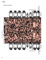
Страница 26: ...26 EMX66M A A MIX66 Circuit Board...
Страница 27: ...27 EMX66M A A Pattern side 3NA V826690 1...
Страница 28: ...28 EMX66M to MIX66 CN901 DSP Circuit Board Component side 3NA V826710 1...
Страница 29: ...29 EMX66M Pattern side 3NA V826710 1...
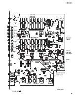
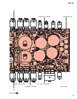
Страница 30: ...30 EMX66M to PWR2 4 W101BE2 to PWR to PWR2 4 W101RE2 to PWR1 4 W103OR1 to MIX66 CN902 A A PWR 1 4 Circuit Board...
Страница 39: ...39 EMX66M...
Страница 40: ...40 EMX66M...
Страница 41: ...41 EMX66M...
Страница 42: ...42 EMX66M...
Страница 43: ...43 EMX66M...
Страница 44: ...44 EMX66M...


