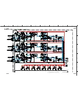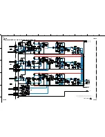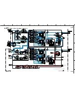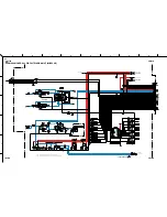
36
EMX66M
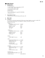
Table 2.12-1
EFFECT
OPERATION
OUTPUT level (MONITOR OUTPUT)
VOCAL ECHO 1
Press the ON switch
No output [DIN AUDIO] -48dBs
VOCAL ECHO 2
Set the LEVEL to minimum
No output [DIN AUDIO] -48dBs
VOCAL REVERB 1
-
Recognizable
VOCAL REVERB 2
-
No output [DIN AUDIO] -48dBs
HALL 1
Switch the FOOT SW
Less than -30 dBs [DIN AUDIO] or full output
HALL 2
-
No output [DIN AUDIO] -48dBs
ROOM
-
Decays 4.2
±
1 dBs from the full output
PLATE
-
Full output; 10
±
3 dBs
•
When each PROGRAM switch is pressed, confirm that the corresponding LED lights up.
•
Apply the music source (vocal etc), and confirm the effect aurally.
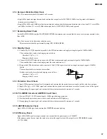
2.13 Stability Check
Note: This mesurement should be performed with a load resistance connected to power amplifier output. (See 3.1.1)
•
At each input terminal, connect 10pF~0.1
µ
F capacitor in parallel to the load resistance, and confirm that the system works
normally without oscillation etc.
•
Set all VR and EQ faders to maximum, and confirm that the system works normally. (Especially, does not oscillate when the EQ
HIGH is set to maximum)
3.
Power Amplifier Check
3.1
For the case that the POWER AMP switch is 'MAIN-MONITOR' or 'MAIN-MAIN'
3.1.1 Preparation
•
INPUT terminal: CH 5 LINE 1
•
POWER AMP switch: MAIN-MAIN
•
OUTPUT terminal: SPEAKERS A1, SPEAKERS B1
•
Load Resistance: 4
Ω
(more than 300W)
Except otherwise indicated, the load resistance should be connected only for the power amplifier check.
•
Set the LEVEL control of CH1-4, 6 to minimum.
•
Except the above, same as the setting of 2.1.
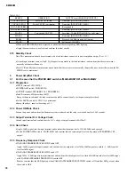
3.1.2 Power ON Mute Check
Turn on the power and confirm that the mute system is released and the relay is switched on after 2.5
±
1 seconds.
3.1.3 Output Terminal D.C. Voltage Check
Ground input terminal and confirm that the D.C. voltage of output terminal is 0
±
100mV.
3.1.4 Gain Check
•
Apply -26dBs signal into the input terminal and confirm that the output level of 20.0
±
2.0dBs can be gained.
•
Set the POWER AMP switch to ’MAIN-MON’ and confirm that the same output level can be gained at SPEAKERS A2, B2
output.
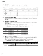
3.1.5 Frequency Response Check
•
YAMAHA SPEAKERS PROCESSING Switch OFF
Apply -26dBs signal info input terminal, and confirm that the output level for 20Hz, 20kHz signal are 1, -3dB from the
level for 1kHz signal.
•
YAMAHA SPEAKERS PROCESSING Switch ON
Apply 70Hz / -26dB signal into input terminal, and confirm that the output level is within 6.5
±
2dB from the level for 1kHz input
with YAMAHA SPEAKERS PROCESSING switch OFF.
Besides, confirm that the LED lights up when YAMAHA SPEAKERS PROCESSING switch is ON and that LED goes out when
the switch is OFF.
Содержание EMX66M
Страница 5: ...5 EMX66M...
Страница 6: ...6 EMX66M...
Страница 11: ...11 EMX66M DIMENSIONS 305mm 481 5mm 448 5mm 327 6mm 62mm Front View Side View Front View with Rack Mount Adaptor...
Страница 26: ...26 EMX66M A A MIX66 Circuit Board...
Страница 27: ...27 EMX66M A A Pattern side 3NA V826690 1...
Страница 28: ...28 EMX66M to MIX66 CN901 DSP Circuit Board Component side 3NA V826710 1...
Страница 29: ...29 EMX66M Pattern side 3NA V826710 1...
Страница 30: ...30 EMX66M to PWR2 4 W101BE2 to PWR to PWR2 4 W101RE2 to PWR1 4 W103OR1 to MIX66 CN902 A A PWR 1 4 Circuit Board...
Страница 39: ...39 EMX66M...
Страница 40: ...40 EMX66M...
Страница 41: ...41 EMX66M...
Страница 42: ...42 EMX66M...
Страница 43: ...43 EMX66M...
Страница 44: ...44 EMX66M...

