15
DXS12/DXS15
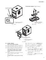
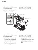
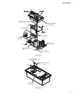
B-6-5 Remove the four (4) screws marked [50] and two (2)
screws marked [60]. The SUBW1 circuit board can
then be removed from the shield ACIN. (Fig. B-5)
*
Be sure to remove binding tie B. Install as before
binding tie B was removed. (Fig. B-5, Fig. B-5-1)
*
When installing the SUBW1 circuit board, fi rst
tighten the two (2) priority screws as shown in
Fig.
B-5.
B-6-6 Remove the power knob from the SUBW1 circuit
board. (Fig. B-5)
B-6-7 Straighten the two claws of the inlet angle and remove
the inlet angle from the SUBW1 circuit board.
(Fig. B-5, Photo B-1)
*
The power knob and the inlet angle are not parts
of the SUBW1 circuit board. When replacing the
SUBW1 circuit board, remove the power knob and
the inlet angle from the SUBW1 circuit board and
install them to the new circuit board. (Fig. B-5)
PRIORITY SCREW
(優先ネジ)
PRIORITY SCREW
(優先ネジ)
SHIELD ACIN
(シールド ACIN)
INLET ANGLE
(インレット金具)
TERMINAL LUG
(ターミナルラグ)
90-degree
(90 度)
POWER KNOB
(パワーノブ)
[50]
[60]
[90]
[90]
SUBW1
[70]
[80]
PRIORITY SCREW
:
(優先ネジ
:
)
PRIORITY SCREW
@
(優先ネジ
@
)
CLAW
(ツメ)
SHIELD ACIN
(シールド ACIN)
Connector Assembly
(束線)
SUBW1
BINDING TIE B
(インシュロックタイ B)
Bond
(ボンド)
CORE
(コア)
SUBW1
CLAW
(ツメ)
※After the connector assembly is fi xed with
binding tie, the bond is spread and fi xed
between the core and the SUBW1 circuit
board.
※インシュロックタイで束線を固定した後、コ
アと SUBW1 シートの間にボンドを塗布し
て固定してください。
※The core is added at location
A
.
The screw at location
B
is covered with bond. After
replacing the SUBW1 circuit board and tightening the
screws, bond as before.
※
A
の箇所にコアが追加されています。
B
の箇所のネジはボンドで覆われています。SUBW1シートを交
換してネジを締めた後、元のようにボンド付けしてください。
Fig. B-5-1
(図B-5-1)
Fig. B-5
(図B-5)
Photo B-1
(写真B-1)
B-6-5 [50] のネジ 4 本と [60] のネジ 2 本を外して、シー
ルド ACIN から SUBW1 シートを外します。
(図 B-5)
※
インシュロックタイ B を必ず外してください。
取り付けるときは、インシュロックタイ B を取り外す前
と同じように取り付けてください。(図 B-5、図 B-5-1)
※
SUBW1 シートを取り付けるときは、図に示す優先ネジ
2 本を先に締めてください。(図 B-5)
B-6-6 SUBW1 シートからパワーノブを外します。
(図 B-5)
B-6-7 インレット金具のツメ 2 箇所をまっすぐに伸ばし
て、SUBW1 シートからインレット金具を外しま
す。(図 B-5、写真 B-1)
※
パワーノブとインレット金具は、SUBW1 シートの構成
部品ではありません。SUBW1 シートを交換する際には、
SUBW1 シートからパワーノブとインレット金具を取り
外して、新しいシートに取り付けてください。(図 B-5)
Содержание DXS Series
Страница 6: ...DXS12 DXS15 6 O 03 66 0 アンプAss y 1 DC ファン 68 68 68 68 036 63 ...
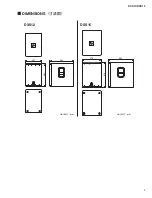
Страница 7: ...7 DXS12 DXS15 DIMENSIONS 寸法図 478 618 624 397 563 594 DXS12 DXS15 Unit 単位 mm Unit 単位 mm ...
Страница 21: ...21 DXS12 DXS15 Pattern side パターン側 AMPSW Circuit Board Scale 90 100 2NA WW65240 2 ...
Страница 23: ...23 DXS12 DXS15 2NA WW59820 3 Pattern side パターン側 DSPW Circuit Board to AMPSW CN255 ...
Страница 58: ...190 170 160 200 220 230 250 360 370 350 370 210 10d 240 Details A A 部詳細 380 7 DXS12 DXS15 ...
Страница 59: ... E E F F D F E E E E E E E D E E 6 66 0 シールド Ass y 03 29 5 66 0 アンプカバー Ass y DXS12 DXS15 8 ...

