23
DXR8/DXR10/DXR12/DXR15
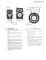
C-7-5 Remove the four (4) screws marked [50] and two (2)
screws marked [60]. The SUB1 circuit board can then
be removed from the shield ACIN. (Fig. C-5)
*
When installing the SUB1 circuit board, fi rst tighten
the two (2) priority screws as shown in Fig. C-5.
C-7-6 Remove the power knob from the SUB1 circuit board.
(Fig. C-5)
C-7-7 Straighten the two claws of the inlet angle and remove
the inlet angle from the SUB1 circuit board. (Fig. C-5,
Photo C-1)
*
The power knob and the inlet angle are not parts of
the SUB1 circuit board. When replacing the SUB1
circuit board, remove the power knob and the inlet
angle from the SUB1 circuit board and install them
to the new circuit board. (Fig. C-5)
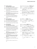
PRIORITY SCREW
(優先ネジ)
PRIORITY SCREW
(優先ネジ)
SHIELD ACIN
(シールド ACIN)
INLET ANGLE
(インレット金具)
TERMINAL LUG
(ターミナルラグ)
90-degree
(90 度)
POWER KNOB
(パワーノブ)
[50]
[60]
[90]
[90]
SUB1
[70]
[80]
PRIORITY SCREW
:
(優先ネジ
:
)
PRIORITY SCREW
@
(優先ネジ
@
)
CLAW
(ツメ)
SUB1
CLAW
(ツメ)
C-7-5 [50] のネジ 4 本と [60] のネジ 2 本を外して、シー
ルド ACIN から SUB1 シートを外します。
(図 C-5)
※
SUB1 シートを取り付けるときは、図に示す優先ネジ 2
本を先に締めてください。(図 C-5)
C-7-6 SUB1 シートからパワーノブを外します。
(図 C-5)
C-7-7 インレット金具のツメ 2 箇所をまっすぐに伸ばし
て、SUB1 シートからインレット金具を外します。
(図 C-5、写真 C-1)
※
パワーノブとインレット金具は、SUB1 シートの構成
部品ではありません。SUB1 シートを交換する際には、
SUB1 シートからパワーノブとインレット金具を取り外
して、新しいシートに取り付けてください。(図 C-5)
Fig. C-5
(図C-5)
Photo C-1
(写真C-1)
Содержание DXR Series
Страница 29: ...29 DXR8 DXR10 DXR12 DXR15 Pattern side パターン側 AMPS Circuit Board Scale 90 100 2NA WW65240 2 ...
Страница 31: ...31 DXR8 DXR10 DXR12 DXR15 2NA WW59820 3 Pattern side パターン側 DSP Circuit Board to AMPS CN255 ...
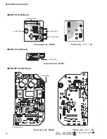
Страница 32: ...DXR8 DXR10 DXR12 DXR15 32 to AMPS CN101 SUB1 Circuit Board 2NA WW65260 4 Component side 部品側 Pattern side パターン側 ...
Страница 73: ... G O HWDLOV A 部詳細 SDUWV RI 100 の部品 7 03 66 0 TWAMP Ass y 6HH SDJH 13 DXR8 DXR10 DXR12 DXR15 ...
Страница 74: ... E E F F D F E E E E E E E D E E 6 66 0 シールド Ass y 03 29 5 66 0 アンプカバー Ass y DXR8 DXR10 DXR12 DXR15 14 ...


