background image


5

Note that you cannot simply use an RS232C or RS422 straight cable or cross-cable 
“as is.” Refer to the pin assignment table above, and change the wiring as needed. 
The cable from the DM1000 must be connected to the “serial mixer control 
connector.” Video editors have a D-sub 9-pin connector for video recorders, but the 
DM1000 cannot be connected to a video recorder connector or to the parallel 
control connector of a video editor. 


3.  Connect the DM1000 V2 to your video recorders 

Connect the audio signals from the video recorders to the DM1000’s audio input 
jacks. You can connect to the DM1000’s analog jacks, or to the analog or digital 
jacks on an MY card. If you’re using a digital video recorder, you can use the 
2TRACK IN jacks, or install a card that allows transmission and reception of 
AES/EBU signals, such as the MY8-AE/AE96/AE96S or MY16-AE. The MY 
cards have D-sub 25-pin connectors (female), so you will need to obtain a cable 
appropriate for the connector you use. 
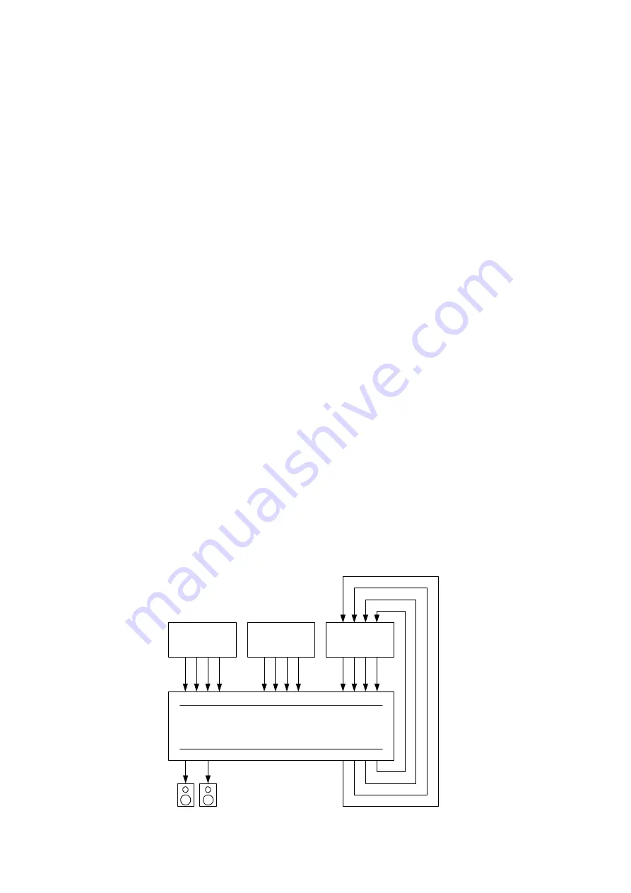
The following explanation will assume that you are using two VTRs for playback 
and one VTR for recording, and that they are connected as follows: 

-


Playback VTR (P1) output connected to INPUT jacks 1, 2, 3, 4 

-


Playback VTR (P2) output connected to INPUT jacks 5, 6, 7, 8 

-


Recording VTR (REC) output connected to INPUT jacks 9, 10, 11, 12 

-


OMNI OUT jacks 1, 2, 3, 4, connected to the inputs of the recording VTR 
(REC) 

(If you’re using an MY card, these will be INPUT jacks 17 and following, so 
substitute the INPUT jack numbers appropriately.) 

VTR

PLAYER1

VTR

RECORDER

VTR

PLAYER2

DM1000

1 2 3 4

9 10 11 12

5 6 7 8

INPUT

1 2 3 4

11

12

OMNI OUT


Содержание DM 1000

Страница 1: ...August 2006 Rev 1 01 Control from a Video Editor Startup Guide...

Страница 2: ...to input channels 9 9 Patch the bus signals to output jacks 10 10 Assign the audio channel inputs for the video recorders and the DM1000 10 11 Specify the fader operation of the DM1000 12 12 Specify...

Страница 3: ...controlled via the ESAM Serial II Protocol ESAM II Extended protocol which is designed to link the operation of video editors and mixers in a post production environment The audio signal crossfade fun...

Страница 4: ...ost cases you can make the appropriate settings for connecting the DM1000 simply by setting your video editor to control the Graham Patten Systems Inc D ESAM which is a typical ESAM compatible mixer 2...

Страница 5: ...order you can use the 2TRACK IN jacks or install a card that allows transmission and reception of AES EBU signals such as the MY8 AE AE96 AE96S or MY16 AE The MY cards have D sub 25 pin connectors fem...

Страница 6: ...ions and settings 4 Enable commands to be exchanged with the video editor In the DISPLAY ACCESS section repeatedly press the SETUP key to access the REMOTE REMOTE PORT SETUP page of the SETUP screen M...

Страница 7: ...DM1000 s LCD screen If this message does not appear change the setting in the screen as described in step 5 3 and try the operation of step 5 1 again If this message appears it means that some type o...

Страница 8: ...e connector Hint If you operate the video editor when the DM1000 V2 is not connected to the video editor the video editor may indicate Mixer Local This indicates that you attempted to control the audi...

Страница 9: ...e them in a scene memory 8 Patch the INPUT jack signals to input channels On the DM1000 the signals connected to the INPUT jacks can be patched to the desired channel In this example the signals from...

Страница 10: ...ample patch buses 1 4 to OMNI OUT jacks 1 4 and patch the control monitor L R channels to 11 12 10 Assign the audio channel inputs for the video recorders and the DM1000 Specify the relationship betwe...

Страница 11: ...Y ACCESS section press the REMOTE key repeatedly to access the ESAM1 32 ESAM MACHINE ASSIGN CH1 32 page and ESAM33 48 ESAM MACHINE ASSIGN CH33 48 page of the REMOTE screen Assign 1 2 3 4 to machine A...

Страница 12: ...actual levels In other words when the crossfade begins the faders will move upward for the channels that are fading in and move downward for the channels that are fading out giving you a visual indica...

Страница 13: ...owever if you are not using pre read you must not send the playback signal from the REC machine to BUS 1 8 since this would cause a signal loop If you are switching between using pre read and not usin...

Страница 14: ...the input signals can be monitored via the stereo bus 13 Set the panning of the signals being input to the DM1000 For the channels routed to the stereo bus set the pan to the monitoring positions If...

Страница 15: ...eo input signal are panned to left and right the monitor signal will also be stereo With the factory settings panning two paired channels to far left and far right will raise the level by approximatel...

Страница 16: ...nnel 16 Adjust the input output levels Here we will set the level balance of the channels that are faded out by crossfading the levels of the FROM machine and of the channels that are faded in by cros...

Страница 17: ...s up to this point simply by recalling the stored scene For details on how to store to a scene memory refer to the DM1000 owner s manual 19 Controlling the system from your video editor From your vide...

Страница 18: ...tion of mode settings will determine how the video editor will be performed and will also determine the mixer commands transmitted from the video editor thus additionally determining how the DM1000 wi...

Отзывы: