10
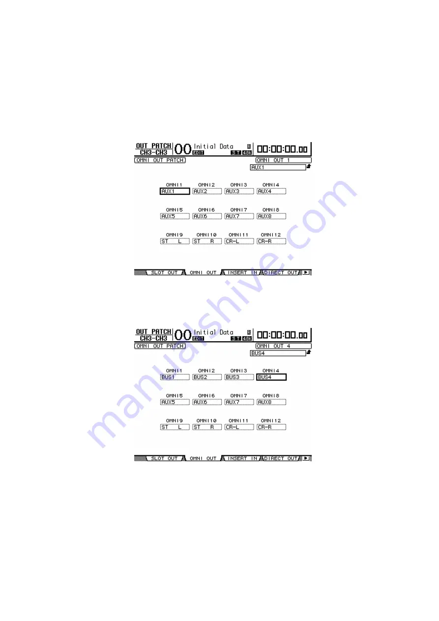
9. Patch the bus signals to output jacks
The crossfaded signals will be routed via buses to the video recorder used for
recording. The playback audio from the video recorder used for recording will be
routed via the stereo bus and output from the monitor speakers. Patch the
appropriate bus to each jack in order to create this output signal routing.
In this example, patch buses 1-4 to OMNI OUT jacks 1-4, and patch the control
monitor L/R channels to 11-12.
10. Assign the audio channel inputs for the video recorders and
the DM1000
Specify the relationship between the DM1000’s INPUT jacks and the video
recorders. Based on these assignments, the DM1000 will interpret commands from
the video editor, and will control the appropriate channel accordingly. (On some
editors such as the BVE9100, these assignments are not used; instead, control will
occur according to the settings of the video editor. These settings are provided by


