


CHASSIS
3-23
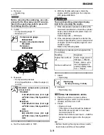
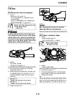
4. Raise the front end of the vehicle so that
there is no weight on the front wheels.
5. Check:
• Ball joints and wheel bearings
Move the wheels laterally back and forth.
Excessive free play
→
Replace the front
arms (upper and lower) and/or wheel
bearings.
EAS29290
ADJUSTING THE TOE-IN
1. Place the vehicle on a level surface.
2. Measure:
• Toe-in
Out of specification
→
Adjust.
▼▼▼▼▼▼▼▼▼▼▼▼▼▼▼▼▼▼▼▼▼▼▼▼▼▼▼▼▼▼
TIP
Before measuring the toe-in, make sure that
the tire pressure is correct.
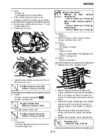
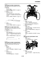
a. Mark both front tire tread centers.
b. Face the handlebar straight ahead.
c. Measure the width “A” between the marks.
d. Rotate the front tires 180
°
until the marks
are exactly opposite one another.
e. Measure the width “B” between the marks.
f.
Calculate the toe-in using the formula given
below.
g. If the toe-in is incorrect, adjust it.
▲▲▲▲▲▲▲▲▲▲▲▲▲▲▲▲▲▲▲▲▲▲▲▲▲▲▲▲▲▲
3. Adjust:
• Toe-in
WARNING
EWA14910
• Be sure that both tie-rods are turned the
same amount. If not, the vehicle will drift
right or left even though the handlebar is
positioned straight. This may lead to mis-
handling and an accident.
• After setting the toe-in to specification,
run the vehicle slowly for some distance
with both hands lightly holding the han-
dlebar and check that the handlebar
responds correctly. If not, turn either the
right or left tie-rod within the toe-in speci-
fication.
▼▼▼▼▼▼▼▼▼▼▼▼▼▼▼▼▼▼▼▼▼▼▼▼▼▼▼▼▼▼
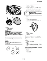
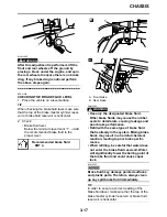
a. Mark both tie-rods ends.
This reference point will be needed during
adjustment.
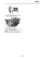
b. Loosen the locknuts (tie-rod end) “1” of
both tie-rods.
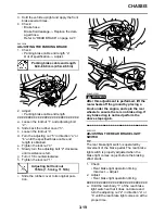
c. The same number of turns should be given
to both the right and left tie-rods “2” until
the specified toe-in is obtained. This is to
keep the length of the rods the same.
Toe-in (with tire touching the
ground)
9.0–19.0 mm (0.35–0.75 in)
Toe-in = “B” – “A”
C. Forward
Содержание 2009 YFM25RY
Страница 1: ...SERVICE MANUAL YFM25RY YFM25RSEY YFM25RSE2Y 4D3 28197 11 LIT 11616 22 09 2009 ...
Страница 8: ......
Страница 39: ...LUBRICATION POINTS AND LUBRICANT TYPES 2 20 ...
Страница 42: ...LUBRICATION SYSTEM CHART AND DIAGRAMS 2 23 EAS20410 LUBRICATION DIAGRAMS ...
Страница 43: ...LUBRICATION SYSTEM CHART AND DIAGRAMS 2 24 1 Camshaft 2 Oil filter element 3 Oil pump 4 Oil strainer ...
Страница 44: ...LUBRICATION SYSTEM CHART AND DIAGRAMS 2 25 ...
Страница 46: ...LUBRICATION SYSTEM CHART AND DIAGRAMS 2 27 ...
Страница 47: ...LUBRICATION SYSTEM CHART AND DIAGRAMS 2 28 1 Oil cooler 2 Oil hose 1 3 Oil hose 2 ...
Страница 48: ...CABLE ROUTING 2 29 EAS20430 CABLE ROUTING ...
Страница 50: ...CABLE ROUTING 2 31 ...
Страница 52: ...CABLE ROUTING 2 33 ...
Страница 54: ...CABLE ROUTING 2 35 ...
Страница 56: ...CABLE ROUTING 2 37 ...
Страница 58: ...CABLE ROUTING 2 39 ...
Страница 60: ...CABLE ROUTING 2 41 ...
Страница 62: ...CABLE ROUTING 2 43 ...
Страница 65: ......
Страница 143: ...HANDLEBAR 4 42 Throttle cable free play 2 0 4 0 mm 0 08 0 16 in ...
Страница 162: ...CHAIN DRIVE 4 61 ...
Страница 165: ......
Страница 240: ...CARBURETOR 6 9 ...
Страница 242: ...IGNITION SYSTEM 7 1 EAS27090 IGNITION SYSTEM EAS27100 CIRCUIT DIAGRAM ...
Страница 246: ...ELECTRIC STARTING SYSTEM 7 5 EAS27160 ELECTRIC STARTING SYSTEM EAS27170 CIRCUIT DIAGRAM ...
Страница 252: ...CHARGING SYSTEM 7 11 EAS27200 CHARGING SYSTEM EAS27210 CIRCUIT DIAGRAM ...
Страница 253: ...CHARGING SYSTEM 7 12 2 Stator coil 3 Rectifier regulator 5 Battery positive lead 6 Battery 7 Fuse 28 Ground ...
Страница 255: ...CHARGING SYSTEM 7 14 ...
Страница 256: ...LIGHTING SYSTEM 7 15 EAS27240 LIGHTING SYSTEM EAS27250 CIRCUIT DIAGRAM ...
Страница 260: ...SIGNALING SYSTEM 7 19 EAS27270 SIGNALING SYSTEM EAS27280 CIRCUIT DIAGRAM ...
Страница 264: ...CARBURETOR HEATING SYSTEM 7 23 EAS27490 CARBURETOR HEATING SYSTEM EAS27500 CIRCUIT DIAGRAM ...
Страница 267: ...CARBURETOR HEATING SYSTEM 7 26 ...
Страница 268: ...ELECTRICAL COMPONENTS 7 27 EAS27972 ELECTRICAL COMPONENTS ...
Страница 270: ...ELECTRICAL COMPONENTS 7 29 EAS27980 CHECKING THE SWITCHES ...
Страница 284: ...ELECTRICAL COMPONENTS 7 43 ...
Страница 291: ......
Страница 292: ...YAMAHA MOTOR CO LTD 2500 SHINGAI IWATA SHIZUOKA JAPAN ...
Страница 293: ...WIRING DIAGRAM YFM25RY YFM25RSEY YFM25RSE2Y ...