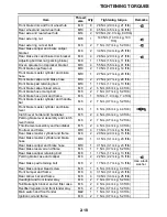

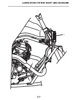
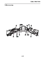


CABLE ROUTING
2-32
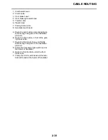
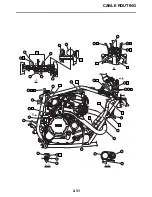
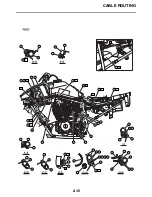
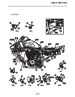
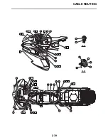
1. Indicator light lead
2. Main switch lead
3. Coupler joint
4. Front brake hose 2
5. Oil cooler hose 1, 2
6. Exhaust pipe
7. Engine bracket
8. Parking brake cable
9. Rear brake light switch lead
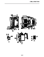
10.Battery negative lead
11.Carburetor warmer lead
12.Air vent hose
13.3 way connector
14.Breather hose
15.Front brake light switch lead
16.Throttle cable
17.Front brake hose 1
18.Clutch cable
19.Main harness
20.Clamp
21.Frame complete
22.Rear brake reservoir hose
23.Carburetor overflow hose
24.Neutral switch lead
25.Rear brake reservoir
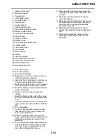
A. To the front panel
B. To the front fender
C. To the right headlight
D. Make sure to route the oil cooler hoses 1
and 2 through the guide wire.
E. Install the front brake hose 2, making sure
to face the white paint mark forward.
F. Route the oil cooler hose 1 and 2 between
the exhaust pipe and the engine bracket.
G. Route the battery negative lead behind the
clutch cable holder.
H. Route the air vent hose through the
bracket.
I. Route the breather hose under the 3 way
connector and outside of the throttle cable
cover.
J. Face the white paint mark on the breather
hose upward. Face the tab of the clip to the
left.
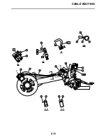
K. To the handlebar
L. Route the throttle cable under the cross
pipe and left of the steering column as
shown in the illustration.
M. Route the parking brake cable and the
clutch cable under the cross pipe and right
of the steering column as shown in the
illustration.
N. When installing the brake pipe, make sure
to have more than 10 mm (0.39 in) clear-
ance from frame complete and steering
stem after tightening the flare nut.
O. When installing the brake pipe, place the
marking on top and tighten the above flare
nut first.
P. Route the rear brake light switch lead
under the bracket.
Q. Route the rear brake light switch lead, neu-
tral switch lead, air vent hose, carburetor
overflow hose and parking brake cable
through the bracket.
R. Route the rear brake light switch lead
between the bracket and rear brake reser-
voir.
S. Route the neutral switch lead and rear
brake light switch lead as shown in the
illustration.
Содержание 2009 YFM25RY
Страница 1: ...SERVICE MANUAL YFM25RY YFM25RSEY YFM25RSE2Y 4D3 28197 11 LIT 11616 22 09 2009 ...
Страница 8: ......
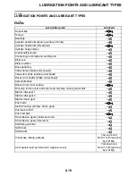
Страница 39: ...LUBRICATION POINTS AND LUBRICANT TYPES 2 20 ...
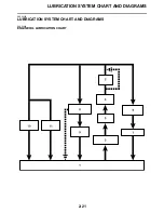
Страница 42: ...LUBRICATION SYSTEM CHART AND DIAGRAMS 2 23 EAS20410 LUBRICATION DIAGRAMS ...
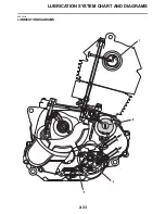
Страница 43: ...LUBRICATION SYSTEM CHART AND DIAGRAMS 2 24 1 Camshaft 2 Oil filter element 3 Oil pump 4 Oil strainer ...
Страница 44: ...LUBRICATION SYSTEM CHART AND DIAGRAMS 2 25 ...
Страница 46: ...LUBRICATION SYSTEM CHART AND DIAGRAMS 2 27 ...
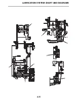
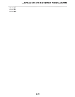
Страница 47: ...LUBRICATION SYSTEM CHART AND DIAGRAMS 2 28 1 Oil cooler 2 Oil hose 1 3 Oil hose 2 ...
Страница 48: ...CABLE ROUTING 2 29 EAS20430 CABLE ROUTING ...
Страница 50: ...CABLE ROUTING 2 31 ...
Страница 52: ...CABLE ROUTING 2 33 ...
Страница 54: ...CABLE ROUTING 2 35 ...
Страница 56: ...CABLE ROUTING 2 37 ...
Страница 58: ...CABLE ROUTING 2 39 ...
Страница 60: ...CABLE ROUTING 2 41 ...
Страница 62: ...CABLE ROUTING 2 43 ...
Страница 65: ......
Страница 143: ...HANDLEBAR 4 42 Throttle cable free play 2 0 4 0 mm 0 08 0 16 in ...
Страница 162: ...CHAIN DRIVE 4 61 ...
Страница 165: ......
Страница 240: ...CARBURETOR 6 9 ...
Страница 242: ...IGNITION SYSTEM 7 1 EAS27090 IGNITION SYSTEM EAS27100 CIRCUIT DIAGRAM ...
Страница 246: ...ELECTRIC STARTING SYSTEM 7 5 EAS27160 ELECTRIC STARTING SYSTEM EAS27170 CIRCUIT DIAGRAM ...
Страница 252: ...CHARGING SYSTEM 7 11 EAS27200 CHARGING SYSTEM EAS27210 CIRCUIT DIAGRAM ...
Страница 253: ...CHARGING SYSTEM 7 12 2 Stator coil 3 Rectifier regulator 5 Battery positive lead 6 Battery 7 Fuse 28 Ground ...
Страница 255: ...CHARGING SYSTEM 7 14 ...
Страница 256: ...LIGHTING SYSTEM 7 15 EAS27240 LIGHTING SYSTEM EAS27250 CIRCUIT DIAGRAM ...
Страница 260: ...SIGNALING SYSTEM 7 19 EAS27270 SIGNALING SYSTEM EAS27280 CIRCUIT DIAGRAM ...
Страница 264: ...CARBURETOR HEATING SYSTEM 7 23 EAS27490 CARBURETOR HEATING SYSTEM EAS27500 CIRCUIT DIAGRAM ...
Страница 267: ...CARBURETOR HEATING SYSTEM 7 26 ...
Страница 268: ...ELECTRICAL COMPONENTS 7 27 EAS27972 ELECTRICAL COMPONENTS ...
Страница 270: ...ELECTRICAL COMPONENTS 7 29 EAS27980 CHECKING THE SWITCHES ...
Страница 284: ...ELECTRICAL COMPONENTS 7 43 ...
Страница 291: ......
Страница 292: ...YAMAHA MOTOR CO LTD 2500 SHINGAI IWATA SHIZUOKA JAPAN ...
Страница 293: ...WIRING DIAGRAM YFM25RY YFM25RSEY YFM25RSE2Y ...