


ELECTRICAL COMPONENTS
7-34
Therefore, always follow these preventive
measures:
• Wear protective eye gear when handling
or working near batteries.
• Charge batteries in a well-ventilated area.
• Keep batteries away from fire, sparks or
open flames (e.g., welding equipment,
lighted cigarettes).
• DO NOT SMOKE when charging or han-
dling batteries.
• KEEP BATTERIES AND ELECTROLYTE
OUT OF REACH OF CHILDREN.
• Avoid bodily contact with electrolyte as it
can cause severe burns or permanent eye
injury.
FIRST AID IN CASE OF BODILY CONTACT:
EXTERNAL
• Skin — Wash with water.
• Eyes — Flush with water for 15 minutes
and get immediate medical attention.
INTERNAL
• Drink large quantities of water or milk fol-
lowed with milk of magnesia, beaten egg
or vegetable oil. Get immediate medical
attention.
ECA4D3F012
• This is a sealed battery. Never remove the
sealing caps because the balance
between cells will not be maintained and
battery performance will deteriorate.
• Charging time, charging amperage and
charging voltage for an VRLA (Valve Reg-
ulated Lead Acid) battery are different
from those of conventional batteries. The
VRLA (Valve Regulated Lead Acid) bat-
tery should be charged as explained in
the charging method illustrations. If the
battery is overcharged, the electrolyte
level will drop considerably. Therefore,
take special care when charging the bat-
tery.
TIP
Since VRLA (Valve Regulated Lead Acid) bat-
teries are sealed, it is not possible to check the
charge state of the battery by measuring the
specific gravity of the electrolyte. Therefore,
the charge of the battery has to be checked by
measuring the voltage at the battery terminals.
1. Remove:
• Seat
• Battery cover
Refer to “GENERAL CHASSIS” on page
4-1.
2. Disconnect:
• Battery leads
(from the battery terminals)
ECA13640
First, disconnect the negative battery lead
“1”, and then positive battery lead “2”.
3. Remove:
• Battery
4. Check:
• Battery charge
▼▼▼▼▼▼▼▼▼▼▼▼▼▼▼▼▼▼▼▼▼▼▼▼▼▼▼▼▼▼
a. Connect a pocket tester to the battery ter-
minals.
TIP
• The charge state of an VRLA (Valve Regu-
lated Lead Acid) battery can be checked by
measuring its open-circuit voltage (i.e., the
voltage when the positive battery terminal is
disconnected).
• No charging is necessary when the open-cir-
cuit voltage equals or exceeds 12.8 V.
b. Check the charge of the battery, as shown
in the charts and the following example.
• Positive tester probe
→
positive battery terminal
• Negative tester probe
→
negative battery terminal
Example
Open-circuit voltage = 12.0 V
Charging time = 6.5 hours
Charge of the battery = 20–30%
Содержание 2009 YFM25RY
Страница 1: ...SERVICE MANUAL YFM25RY YFM25RSEY YFM25RSE2Y 4D3 28197 11 LIT 11616 22 09 2009 ...
Страница 8: ......
Страница 39: ...LUBRICATION POINTS AND LUBRICANT TYPES 2 20 ...
Страница 42: ...LUBRICATION SYSTEM CHART AND DIAGRAMS 2 23 EAS20410 LUBRICATION DIAGRAMS ...
Страница 43: ...LUBRICATION SYSTEM CHART AND DIAGRAMS 2 24 1 Camshaft 2 Oil filter element 3 Oil pump 4 Oil strainer ...
Страница 44: ...LUBRICATION SYSTEM CHART AND DIAGRAMS 2 25 ...
Страница 46: ...LUBRICATION SYSTEM CHART AND DIAGRAMS 2 27 ...
Страница 47: ...LUBRICATION SYSTEM CHART AND DIAGRAMS 2 28 1 Oil cooler 2 Oil hose 1 3 Oil hose 2 ...
Страница 48: ...CABLE ROUTING 2 29 EAS20430 CABLE ROUTING ...
Страница 50: ...CABLE ROUTING 2 31 ...
Страница 52: ...CABLE ROUTING 2 33 ...
Страница 54: ...CABLE ROUTING 2 35 ...
Страница 56: ...CABLE ROUTING 2 37 ...
Страница 58: ...CABLE ROUTING 2 39 ...
Страница 60: ...CABLE ROUTING 2 41 ...
Страница 62: ...CABLE ROUTING 2 43 ...
Страница 65: ......
Страница 143: ...HANDLEBAR 4 42 Throttle cable free play 2 0 4 0 mm 0 08 0 16 in ...
Страница 162: ...CHAIN DRIVE 4 61 ...
Страница 165: ......
Страница 240: ...CARBURETOR 6 9 ...
Страница 242: ...IGNITION SYSTEM 7 1 EAS27090 IGNITION SYSTEM EAS27100 CIRCUIT DIAGRAM ...
Страница 246: ...ELECTRIC STARTING SYSTEM 7 5 EAS27160 ELECTRIC STARTING SYSTEM EAS27170 CIRCUIT DIAGRAM ...
Страница 252: ...CHARGING SYSTEM 7 11 EAS27200 CHARGING SYSTEM EAS27210 CIRCUIT DIAGRAM ...
Страница 253: ...CHARGING SYSTEM 7 12 2 Stator coil 3 Rectifier regulator 5 Battery positive lead 6 Battery 7 Fuse 28 Ground ...
Страница 255: ...CHARGING SYSTEM 7 14 ...
Страница 256: ...LIGHTING SYSTEM 7 15 EAS27240 LIGHTING SYSTEM EAS27250 CIRCUIT DIAGRAM ...
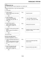
Страница 260: ...SIGNALING SYSTEM 7 19 EAS27270 SIGNALING SYSTEM EAS27280 CIRCUIT DIAGRAM ...
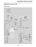
Страница 264: ...CARBURETOR HEATING SYSTEM 7 23 EAS27490 CARBURETOR HEATING SYSTEM EAS27500 CIRCUIT DIAGRAM ...
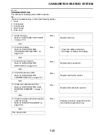
Страница 267: ...CARBURETOR HEATING SYSTEM 7 26 ...
Страница 268: ...ELECTRICAL COMPONENTS 7 27 EAS27972 ELECTRICAL COMPONENTS ...
Страница 270: ...ELECTRICAL COMPONENTS 7 29 EAS27980 CHECKING THE SWITCHES ...
Страница 284: ...ELECTRICAL COMPONENTS 7 43 ...
Страница 291: ......
Страница 292: ...YAMAHA MOTOR CO LTD 2500 SHINGAI IWATA SHIZUOKA JAPAN ...
Страница 293: ...WIRING DIAGRAM YFM25RY YFM25RSEY YFM25RSE2Y ...