3-18
CHASSIS
CHASSIS
EAA00810
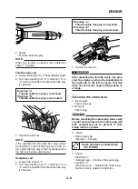
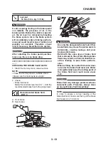
ADJUSTING THE FRONT BRAKE
1. Adjust:
• Brake lever position (distance ”a” from the
throttle grip to the brake lever)
a. While pushing the brake lever forward, turn
the adjusting dial “1” until the brake lever is
in the desired position.
NOTE:
Be sure to align the setting on the adjusting di-
al with the arrow mark “2” on the brake lever
holder.
▼▼▼▼▼▼▼▼▼▼▼▼▼▼▼▼▼▼▼▼▼▼▼▼▼▼▼▼▼▼▼▼
Position #1
Distance “a” is the largest.
Position #5
Distance “a” is the smallest.
WARNING
After adjusting the brake lever position,
make sure that the pin on the brake lever
holder is firmly inserted in the hole in the
adjusting dial.
CAUTION:
After adjusting the brake lever position,
make sure that there is no brake drag.
WARNING
A soft or spongy feeling in the brake lever
can indicate the presence of air in the
brake system. Before the vehicle is operat-
ed, the air must be removed by bleeding
the brake system. Air in the brake system
will considerably reduce braking perform-
ance and could result in loss of control and
possibly an accident. Therefore, check the
brake system and bleed if necessary.
▼▼▼▼▼▼▼▼▼▼▼▼▼▼▼▼▼▼▼▼▼▼▼▼▼▼▼▼▼▼▼▼
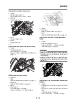
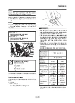
2. Adjust:
• Brake pedal position
b
a
c
2
1
Brake pedal position (below
the top of the rider footrest)
26.8 mm (1.05 in)
▼▼▼▼▼▼▼▼▼▼▼▼▼▼▼▼▼▼▼▼▼▼▼▼▼▼▼▼▼▼▼▼
a. Loosen the locknut “1”.
b. Turn the adjusting bolt “2” in direction “b” or
“c” until the specified brake pedal position is
obtained.
c. Tighten the locknut “1” to the specified
torque.
Direction “b”
Brake pedal is raised.
Direction “c”
Brake pedal is lowered.
EAS00110
ADJUSTING THE REAR BRAKE PEDAL
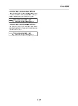
1. Check:
• Brake pedal position (distance “a” from the
top of the rider footrest to the top of the
brake pedal)
Out of specification
→
Adjust.
Содержание 2008 Tenere
Страница 1: ...SERVICE MANUAL 2008 11D F8197 E0 XT660Z ...
Страница 8: ......
Страница 24: ......
Страница 44: ...2 20 TIGHTENING TORQUES Cylinder head tightening sequence 2 4 3 1 ...
Страница 52: ...2 28 COOLING SYSTEM DIAGRAMS EAS00033 COOLING SYSTEM DIAGRAMS 5VK 5VK00 A 4 A B 4 3 2 1 2 3 1 A A A ...
Страница 54: ...2 30 COOLING SYSTEM DIAGRAMS 1 2 3 4 5 6 7 9 10 11 12 5 8 11 A ...
Страница 57: ...2 33 LUBRICATION DIAGRAMS LUBRICATION DIAGRAMS 1 A A A A B B B A A B 3 2 2 4 1 1 5 5 ...
Страница 59: ...2 35 LUBRICATION DIAGRAMS A A A A 3 1 2 3 4 ...
Страница 60: ...2 36 LUBRICATION DIAGRAMS 1 Oil delivery pipe 2 2 Oil delivery pipe 1 3 Oil filter 4 Oil pump ...
Страница 61: ...2 37 LUBRICATION DIAGRAMS 1 7 2 3 4 5 6 A ...
Страница 63: ...2 39 LUBRICATION DIAGRAMS 1 6 5 4 3 2 ...
Страница 64: ...2 40 LUBRICATION DIAGRAMS 1 Camshaft 2 Oil delivery pipe 1 3 Oil filter 4 Main axle 5 Drive axle 6 Crankshaft ...
Страница 65: ...2 41 CABLE ROUTING CABLE ROUTING ...
Страница 67: ...2 43 CABLE ROUTING ...
Страница 69: ...2 45 CABLE ROUTING ...
Страница 71: ...2 47 CABLE ROUTING ...
Страница 73: ...2 49 CABLE ROUTING ...
Страница 75: ...2 51 CABLE ROUTING ...
Страница 77: ...2 53 CABLE ROUTING ...
Страница 79: ...2 55 CABLE ROUTING ...
Страница 81: ...2 57 CABLE ROUTING ...
Страница 83: ...2 59 CABLE ROUTING ...
Страница 84: ...2 60 CABLE ROUTING 1 Bolt union 2 Brake hose 3 Rear stop switch 4 Clamp hose A Add Loctite 243 ...
Страница 176: ...4 56 FRONT FORK WARNING Make sure the brake hoses are routed prop erly 1 2 3 ...
Страница 270: ......
Страница 284: ......
Страница 301: ...7 17 FUEL INJECTION SYSTEM WIRING DIAGRAM ...
Страница 324: ......
Страница 327: ...8 1 IGNITION SYSTEM EAS27090 IGNITION SYSTEM EAS27110 CIRCUIT DIAGRAM ...
Страница 331: ...8 5 ELECTRIC STARTING SYSTEM EAS27160 ELECTRIC STARTING SYSTEM EAS27170 CIRCUIT DIAGRAM ...
Страница 337: ...8 11 CHARGING SYSTEM EAS27200 CHARGING SYSTEM EAS27210 CIRCUIT DIAGRAM ...
Страница 338: ...8 12 CHARGING SYSTEM 2 A C magneto 5 Rectifier regulator 7 Battery 8 Main fuse ...
Страница 340: ...8 14 CHARGING SYSTEM ...
Страница 341: ...8 15 LIGHTING SYSTEM EAS27240 LIGHTING SYSTEM EAS27250 CIRCUIT DIAGRAM ...
Страница 345: ...8 19 SIGNALING SYSTEM EAS27270 SIGNALING SYSTEM EAS27280 CIRCUIT DIAGRAM ...
Страница 351: ...8 25 COOLING SYSTEM EAS00807 COOLING SYSTEM CIRCUIT DIAGRAM ...
Страница 354: ...8 28 COOLING SYSTEM ...
Страница 355: ...8 29 IMMOBILIZER SYSTEM ET5YU1002 IMMOBILIZER SYSTEM ET5YU1003 CIRCUIT DIAGRAM ...
Страница 364: ...8 38 IMMOBILIZER SYSTEM ...
Страница 365: ...8 39 ELECTRICAL COMPONENTS EAS27970 ELECTRICAL COMPONENTS ...
Страница 367: ...8 41 ELECTRICAL COMPONENTS ...
Страница 369: ...8 43 ELECTRICAL COMPONENTS EAS27980 CHECKING THE SWITCHES ...
Страница 388: ......
Страница 390: ......
Страница 396: ...COLOR CODE ...
Страница 397: ......
Страница 398: ...YAMAHA MOTOR ITALIA S P A ...
Страница 399: ...XT660Z 2008 WIRING DIAGRAM ...


