background image

P

anel Oper

ation and Displa

y

s

Utility Displays

DME64N/DME24N Owner’s Manual

52

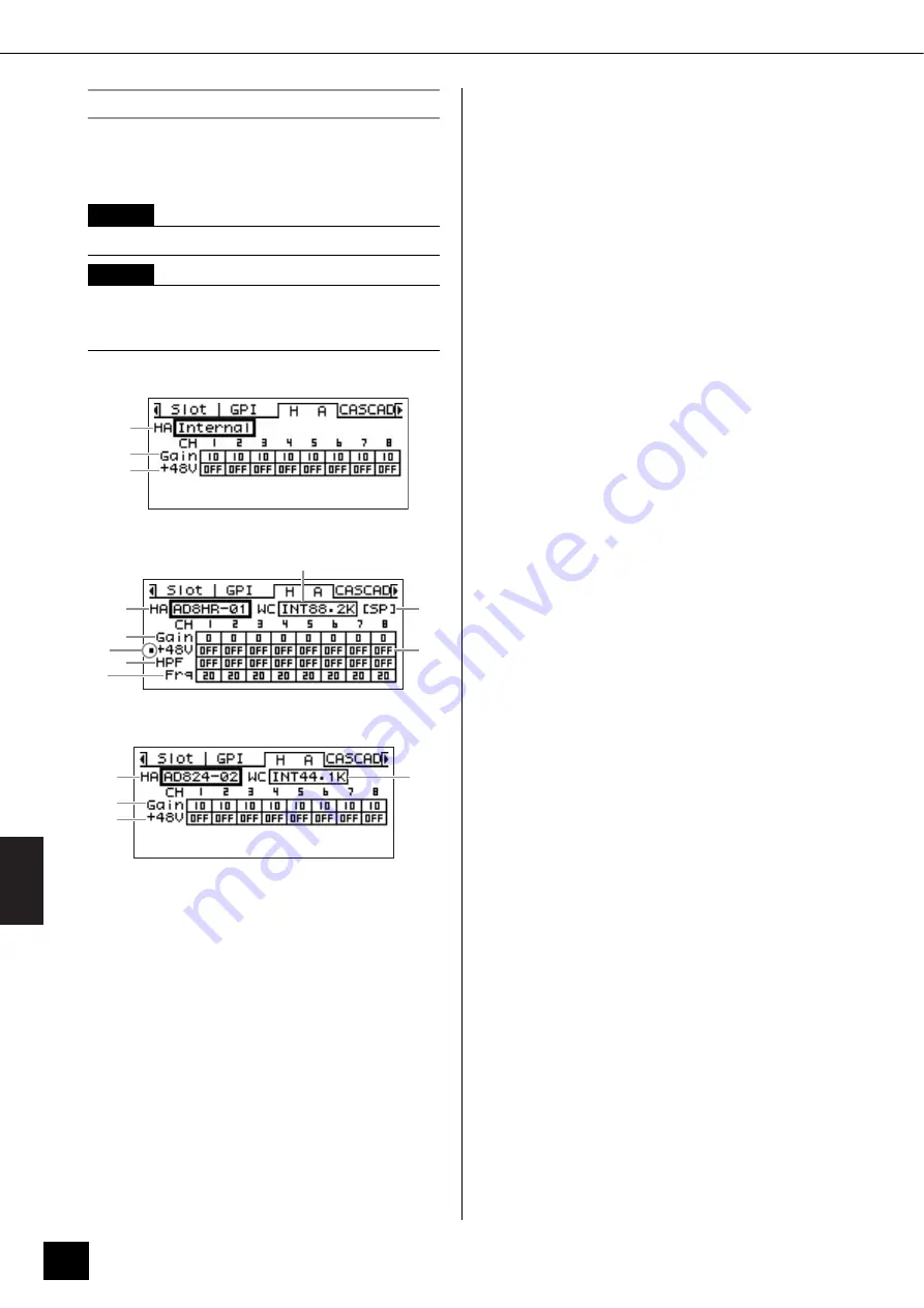
Head Amplifier Setup (HA) Page

Provides access to the head amplifier settings. Refer to 
“REMOTE Connection” on page 28 for head amplifier 
control signal connection.

Internal Head Amplifier (DME24N only)

AD8HR

AD824

1

HA

Specifies the type of head amplifier to be set up. The 
available options are AD8HR, AD824, and Built-in HA 
(DME24N only). When the AD8HR and AD824 are 
selected, a number indicating the connection order will 
also appear.
Edit using the “List Parameters” editing procedure 
described on page 38.

2

WCLK (AD8HR/AD824 only)

Specifies the word clock signal to be used by the head 
amplifier(s).

Available settings of the AD8HR are “D OUT A,” “WCLK 
IN,” “INT44.1K,” “INT48K,” “INT88.2K,” and “INT96K.” 

D OUT A:

 Sets the word clock signal at the digital 

input as the master clock of the AD8HR.

WCLK IN:

 Sets the word clock signal at BNC 

connector as the master clock of the AD8HR.

INT44.1K:

 Sets the 44.1 kHz internal word clock as 

the master clock of the AD8HR.

INT48K:

 Sets the 48 kHz internal word clock as the 

master clock of the AD8HR.

INT88.2K:

 Sets the 88.2 kHz internal word clock as 

the master clock of the AD8HR.

INT96K:

 Sets the 96 kHz internal word clock as the 

master clock of the AD8HR.

Available settings of the AD824 are “SLOT,” “BNC,” 
“INT44.1K,” and “INT48K.”

SLOT A:

 Sets the word clock signal input via I/O 

cards installed in the I/O slots as the master clock 
of the AD824.

BNC:

 Sets the word clock signal at the BNC 

connector as the master clock of the AD824.

INT44.1K:

 Sets the 44.1 kHz internal word clock as 

the master clock of the AD824.

INT48K:

 Sets the 48 kHz internal word clock as the 

master clock of the AD824.

3

Format (AD8HR only)

Displays the 88.2/96 kHz audio signal transfer mode. 
The input setting is on the left and the output setting is 
on the right.

No Display (default):

 44.1/48 kHz audio signal 

transfer.

SP (Double Speed):

 Allows direct transfer at 88.2 

or 96 kHz.

CH (Double Channel):

 88.2 or 96 kHz audio is 

transferred by using two 44.1/48 kHz channels to 
transfer each audio channel of 88.2 and 96 kHz 
respectively. The number of audio channels that 
can be handled in this mode is half the number of 
channels normally handled by the AD8HR.

4

Gain

Individually sets the gain of each head amplifier channel.
Edit using the “Numeric Parameters” editing procedure 
described on page 36.

NOTE

This page will not appear on the ICP1 display.

NOTE

Some scenes include head amplifier settings. In such 
cases, the HA page settings will be saved along with the 
scene when it is stored.

1

4
5

1

3

2

5

4

7

8

6

1

2

4
5

Содержание 1009MWTO-F0

Страница 1: ...EN Owner s Manual DIGITAL MIXING ENGINE ...

Страница 2: ...es and a third grounding prong The wide blade or the third prong are provided for your safety If the provided plug does not fit into your outlet consult an electrician for replacement of the obsolete outlet 10 Protect the power cord from being walked on or pinched particularly at plugs convenience receptacles and the point where they exit from the apparatus 11 Only use attachments accessories spec...

Страница 3: ...roceed as follows The wire which is coloured GREEN and YELLOW must be connected to the terminal in the plug which is marked by the letter E or by the safety earth symbol or colored GREEN or GREEN and YELLOW The wire which is coloured BLUE must be connected to the terminal which is marked with the letter N or coloured BLACK The wire which is coloured BROWN must be connected to the termi nal which i...

Страница 4: ...ected by Yamaha service personnel The power cord or plug becomes frayed or damaged It emits unusual smells or smoke Some object has been dropped into the instrument There is a sudden loss of sound during use of the device If this device should be dropped or damaged immediately turn off the power switch disconnect the electric plug from the outlet and have the device inspected by qualified Yamaha s...

Страница 5: ...retained even if the backup battery fails Do not turn the POWER switch on and off repeatedly and rapidly Be sure to wait six seconds or more between turning the power to the unit off and then on Always turn the power off when the device is not in use The performance of components with moving contacts such as switches volume controls and connectors deteriorates over time Consult qualified Yamaha se...

Страница 6: ...e of audio processing applications institutional audio installations sub mixing speaker system control matrix and routing multi effect processing and much more In order to take full advantage of the features and performance provided by the DME64N 24N we urge you to read this owner s manual thoroughly before use and keep it in a safe place for future reference The Yamaha Pro Audio web site is at ht...

Страница 7: ...onnectors 30 Cascade Connection Cascade Connectors DME64N only 31 WORD CLOCK Connection WORD CLOCK Connectors 32 GPI Connection GPI Connectors 33 Panel Operation and Displays 34 Basic Operation 34 Main Display 35 Parameter Edit Displays 36 Editing User Defined Button 38 Mute Switching 39 Output Level Control 39 Scene Recall 39 Scene Store 40 Monitoring 40 Spectrum Display 41 Level Meter Display 42...

Страница 8: ...4N 24N then plug the male plug into an appropriate AC mains outlet Be sure to use the voltage specified for the device Turning the power on and off 1 Press the POWER switch to turn on the power to the DME64N 24N 2 Press the POWER switch again to turn off the power Foreword NOTE For more information on your Control Panel refer to the owner s manual that came with the Control Panel as well as the DM...

Страница 9: ...ustic system is called an area Each device group always includes one DME series unit that functions as the group master and controls all other DME series units in the same device group If a computer is connected to the network you can use the computer to control an entire device group via the group master Glossary for the DME64N 24N This section explains terminology specific to the DME64N 24N Comp...

Страница 10: ... change 16 x 8 Scene Scene 1 Scene 2 Scene 999 Component Configuration Preset Parameter Ex Gate Attack Decay Range Threshold Key in Hold Matrix Mixer 96kHz 88 2kHz 48kHz 44 1kHz EXT CLOCK MID MASTER NETWORK PEAK SIGNAL PEAK SIGNAL IN OUT SCENE NUMBER 1 2 3 4 5 6 7 8 1 2 3 4 5 6 7 8 96kHz 88 2kHz 48kHz 44 1kHz EXT CLOCK MID MASTER NETWORK PEAK SIGNAL PEAK SIGNAL IN OUT SCENE NUMBER 1 2 3 4 5 6 7 8 ...

Страница 11: ...nd remote head amp control signals handled via the REMOTE connec tor Type of signals handled by the DME64N 24N Connector Audio Signal Device Control Word Clock Reference Page USB Connector Control signals between computer and DNE64N 24N MIDI messages 22 NETWORK Connector Control signals between computer and DNE64N 24N Control signals between DME series unit Control signals with a controller such a...

Страница 12: ...AL SIGNAL PEAK PEAK SIGNAL SIGNAL PEAK PEAK SIGNAL SIGNAL INPUT INPUT DIGITAL MIXING ENGINE SATELLITE USB PEAK PEAK SIGNAL SIGNAL PEAK PEAK SIGNAL SIGNAL PEAK PEAK SIGNAL SIGNAL INPUT INPUT DIGITAL MIXING ENGINE SATELLITE USB PEAK PEAK SIGNAL SIGNAL PEAK PEAK SIGNAL SIGNAL PEAK PEAK SIGNAL SIGNAL INPUT INPUT DIGITAL MIXING ENGINE SATELLITE DME8o C DME8o C DME8o C DME8o C DME8i C DME8i C DME8i C DM...

Страница 13: ... After the data is transmitted you can disconnect the DME series unit from the computer and use it as an independent processor You can also connect it to a computer and control it in realtime from DME Designer If multiple DME series units are connected in the network DME Designer enables you to build a configura tion that includes those units Please download the DME Designer application driver DME...

Страница 14: ...ill light green If a problem with the master clock is detected all of these indicators will flash red 2 seconds after a problem is detected with an external master clock the internal clock will temporarily be selected When this happens the indicator corresponding to the frequency of the internal clock will light green and all other indicators will continue to flash red 4 NETWORK Indicator Lights w...

Страница 15: ...lls the output level display If this button is held for longer than 2 seconds while the main display is showing the utility display will appear Switches between the Utility display pages if pressed while the Utility display is showing LEVEL Button Calls the output level setup display page 39 The indicator will light green MUTE Button Calls the mute display page 39 The indicator will light orange w...

Страница 16: ...nal Output channels each have an OUT terminal and a GND terminal The open voltage at the V terminal is 5V while the IN terminal detects voltage changes from 0V 5V The OUT terminals output either signal L or H at a TTL level See GPI Connection GPI Connectors on page 33 for connection details 4 MIDI IN MIDI OUT MIDI THRU Connectors These are standard MIDI connectors that handle reception and transmi...

Страница 17: ...a the IN connectors while the OUT connectors can deliver analog output to powered speakers or recording equipment 48V phantom power can be supplied to the IN connectors page 51 Refer to page 26 for IN and OUT connection details 9 I O Slots Optional Yamaha or third party mini YGDAI cards can be plugged in here for system expansion The DME64N has four I O slots while the DME24N has one One expansion...

Страница 18: ...ent depending on the country in which it is purchased a third prong may be provided for grounding purposes Improper connection of the grounding conductor can create the risk of electrical shock Do NOT modify the plug provided with the DME64N 24N If the plug will not fit the outlet have a proper outlet installed by a qualified electrician Do not use a plug adapter which defeats the grounding conduc...

Страница 19: ...wer off No information will appear on the display the first time the device is turned on The appropriate scene and other data must first be transferred to the device from the DME Designer Refer to the DME Setup Manual PDF file for details Once the appropriate data has been transferred to the device the current number and name will appear on the display If any scene data has been stored in the DME6...

Страница 20: ...e serial number A fee is charged for the hardware upgrade For details contact Yamaha customer support using the contact information located at the end of the DME64N 24N Owner s Manual For the latest information on what cards can be used with the DME64N 24N visit the Yamaha Pro Audio website at http www yamahaproaudio com Card Name Function Input Output No of Available Cards DME64N DME24N MY8 AT AD...

Страница 21: ...s shown in the diagram and push the card into the slot Be sure to push the card all the way back into the slot so that the card contacts make proper contact with the slot connector 4 Secure the card with the attached screws Be sure to tighten the screws securely If the screws are left loose proper contact may be lost and malfunction of damage may result NOTE The slot cover and screws will need to ...

Страница 22: ...a Be sure to wait six seconds or more between turning the power to the unit on and then off or off and then on or between connecting and disconnecting or vice versa the USB cable Connecting to a Computer NOTE Refer to the DME Setup Manual PDF file for details on installing USB MIDI Driver and DME Designer Make sure that the USB MIDI Driver s THRU setting is OFF NOTE The computer on which DME Desig...

Страница 23: ...ch A cross cable or straight cable can be used since the DME series supports Auto MDI MDI X In this case set Link Mode on both units to the same setting Devices in different subnet different network address groups can be connected via a router or layer 3 compliant network switch NOTE Refer to the DME Setup Manual PDF file for details on installing DME N Network Driver Appropriate IP addresses must...

Страница 24: ...SIGNAL PEAK PEAK SIGNAL SIGNAL INPUT INPUT DIGITAL MIXING ENGINE SATELLITE HOME HOME UTILITY UTILITY SCENE SCENE LEVEL LEVEL MUTE MUTE ENTER ENTER CANCEL CANCEL Device Group Group Master DME Satellite IP address 192 168 0 7 Ethernet Cable Network Switch Ethernet Cable Computer IP address 192 168 0 100 Ethernet Cable Ethernet Cable DME Satellite IP address 192 168 0 3 Master ID 7 DME64N 24N IP addr...

Страница 25: ...NCEL USB PEAK PEAK SIGNAL SIGNAL PEAK PEAK SIGNAL SIGNAL PEAK PEAK SIGNAL SIGNAL INPUT INPUT DIGITAL MIXING ENGINE SATELLITE USB PEAK PEAK SIGNAL SIGNAL PEAK PEAK SIGNAL SIGNAL PEAK PEAK SIGNAL SIGNAL INPUT INPUT DIGITAL MIXING ENGINE SATELLITE Device Group 1 Device Group 2 Group Master DME Satellite IP address 192 168 0 2 Group Master DME Satellite IP address 192 168 0 3 Ethernet Cable Ethernet C...

Страница 26: ...trip the wire as shown in the illustration and use stranded wire to make connections With a Euroblock connection the stranded wire may be prone to breakage because of metal fatigue due to the weight of the cable or due to vibration When rack mounting your equipment use a lacing bar when possible to bundle and fasten the cables If cables will be frequently connected and disconnected as in the case ...

Страница 27: ...lots and the DME24N has one I O card slot The number of audio input channels available on the DME64N 24N can be increased by plugging the appropriate mini YGDAI I O card s into the available card slot s Some types of cards also provide control and or word clock transmission and reception functionality Refer to Compatible I O cards page 20 for details on the cards that can be used For details on ho...

Страница 28: ...Designer Up to eight AD8HR AD824 head amplifiers can be connected When connecting to a combination of AD8HR and AD824 head amplifiers be sure to place the AD8HR units closest to the DME64N 24N in the chain otherwise the AD8HR or AD824 unit s may not be properly rec ognized by the DME64N 24N For details about the settings refer to the Ext HA Ctrl in Remote page on page 49 Connecting to an External ...

Страница 29: ...damage the unit NOTE Only one mixer can be connected within each device group The digital mixer can be connected to any DME series unit whether it is the group master or a slave unit The ID number of the DME series unit being remotely controlled is specified from DME Designer For details on making this setting refer to the DME Designer Owner s Manual If the connection between DME series units is b...

Страница 30: ...connectors MIDI commands are sent to the DME64N 24N from a MIDI device Refer to MIDI Page on page 49 for MIDI setup details By connecting the MIDI OUT terminal of a digital mixer such as the DM2000 to the MIDI OUT of the DME64N 24N and making the proper settings on the mixer and the DME64N 24N you can change scenes by sending program change messages from the mixer If the MIDI OUT connector of the ...

Страница 31: ...not connect CASCADE IN to CASCADE IN or CASCADE OUT to CASCADE OUT Cascade Connection Example NOTE Maximum length by the optional dedicated Cascade cables Unidirectional Cascade connection 200m 44 1 48kHz 100m 88 2 96kHz Bidirectional Cascade connection 100m 44 1 48kHz 30m 88 2 96kHz NOTE Never create a full cascade loop using only DME64N units NOTE It is also possible to remotely control DME seri...

Страница 32: ...Box Connection Daisy Chain Connection NOTE Word clock can also be received and transmitted via a mini YGDAI card installed in an I O slot or the CASCADE IN and CASCADE OUT connectors It is necessary to specify whether the DME64N 24N will use the internal word clock or an external word clock for synchronization NOTE A device transmitting the word clock signal that will be used by other devices for ...

Страница 33: ...re assigned via the DME Designer application Euroblock connectors are used for all GPI input and output connections Euroblock connection methods are described in Euroblock Connection on page 26 in this manual NOTE For more information on the CP4SW CP4SF and CP1SF control panels refer to CP4SW CP4SF and CP1SF in the Appendix of this manual page 51 NOTE The DME Designer can be used to set up the sys...

Страница 34: ...tton pages MUTE button Mute Display page 39 LEVEL button Output Level Display page 39 SCENE button Scene Recall Display page 39 Scene Store Display page 40 These buttons can be pressed from the Main or Utility displays to directly call the related parameter edit displays MONITOR button Monitor Point Selection Display page 40 This function is useful for level monitoring When the button is pressed t...

Страница 35: ... inverted A maximum of 24 buttons can be made available for user control but only six buttons can be shown in any one display page Press the HOME button to switch to other available button pages A maximum of 8 one byte Roman characters can be displayed in a button name When two byte characters are to be used for languages such as Japanese the total number of displayable characters is reduced accor...

Страница 36: ...arameter a fader knob or minimum and maximum values may appear to the left of the numeric value A Numeric Value with a fader A Numeric Value with a Knob 1 Name of parameter selected for editing 2 Fader 3 Knob 4 Minimum and maximum values 5 Current value Panel Lock The panel controls can be locked to prevent accidental mis operation To activate the panel lock function simultaneously press and hold ...

Страница 37: ...tons E F to select the value to be edited 2 Rotate the dial to edit the value as required 3 Repeat step 1 to select the next value to be edited use the dial to edit as required and repeat until all values have been edited as required 4 When all values have been edited press the ENTER button A confirmation window will appear press ENTER one more time to confirm the edits and close the window Parame...

Страница 38: ...rm the selection and close the window Parameter Edit displays will also appear when the SCENE MUTE MONITOR or other button is pressed These allow scene changes level adjustment and other settings to be edited as required Editing User Defined Button 1 If the Main display is not showing press the HOME button to recall it 2 Press the HOME button until the page containing the parameter to be edited ap...

Страница 39: ...ng Scene Recall This procedure recalls a new scene refer to page 10 1 Press the SCENE button The Scene Recall display will appear 2 Select a new scene Scenes are selected as described in the List Parameters section on page 38 3 Press the ENTER button A confirmation window will appear 4 Press the ENTER button again The new scene will be selected Don t turn the power off during a scene recall operat...

Страница 40: ...select 5 by editing the Monitoring Point List in DME Designer NOTE Scenes can also be changed from a computer or GPI MIDI controller connected to the device The DME Designer application is used to make scene changes from a computer If a GPI MIDI controller is to be used for changes it must be initially set up for scene change control by using the DME Designer NOTE If head amplifier parameters are ...

Страница 41: ...eparate frequency bands Output level is displayed in 12 steps 3 Peak Hold When the peak hold function is ON peak levels since the current monitor point was selected are held indefinitely Peak levels are cleared after one second when peak hold is OFF To turn the peak hold function ON or OFF move the cursor to the PEAK HOLD ON OFF setting and press the ENTER button to alternately turn it ON or OFF 4...

Страница 42: ...s and continue to hold those buttons until the Yamaha logo appears The initialization screen will appear allowing you to choose one of the following three options 01 Initialize DME All scenes preset parameter settings and WAVE files except components and files saved via the File Storage function will be deleted All UTILITY settings are reset to their default values 02 Delete All Data All internall...

Страница 43: ... for settings not included in other pages Page 48 Scene Store Current status and setup for scene store accessibility Last Mem Resume Indicates and determines whether the previous memory contents will be retained when the unit is restarted Event Scheduler Current status and setup whether an event schedule setup in the DME Designer will be executed or not Remote Rmt Ctrl Displays sets the connector ...

Страница 44: ...ys the audio format 88 2 96 kHz Gain Current status and setup for individual head amplifier channel gain 48V Current status and setup for individual head amplifier channel phantom power supply 48V ON OFF no title Displays current status of the master phantom power switch HPF Current status and setup for individual head amplifier channel high pass filter on off Frq Current status and setup for indi...

Страница 45: ...calendar can be set here Edit using the Numeric Parameters editing procedure described on page 36 4 Battery Shows the status of the internal battery Low Battery will appear when the battery needs to be replaced and No Battery will appear when no battery is present in the device 5 Daylight Saving Time If you enable daylight saving time the display will indicate DST You can enable daylight saving ti...

Страница 46: ...on page 38 5 MAC Adr This is the device s MAC Media Access Control address Display Setup Disp Page Provides access to a number of display parameters 1 LCD Contrast The current LCD contrast setting This parameter can be adjusted from 0 through 100 Edit using the Numeric Parameters editing procedure described on page 36 NOTE Device group status of ICP1 is fixed to Slave This cannot be changed NOTE M...

Страница 47: ...om the Unlock mode to the Lock mode 2 Panel Lock Boot Determines whether or not panel lock will be on when power to the device is turned on This parameter can be set to Unlock or Lock Unlock Panel lock is OFF when power to the device is turned on Lock Panel lock is ON when power to the device is turned on 3 Panel Lock Target Determines the controls control functions to be affected by panel lock Th...

Страница 48: ... will be executed OFF The event schedule will not be executed Edit using the List Parameters editing procedure described on page 38 Remote Control Setup Remote Page 1 Rmt Ctrl Remote Control Displays sets the connector and connection type to be used for DME remote control protocol communication If the selected terminal was previously assigned to a different function a confirmation dialog will appe...

Страница 49: ...Also don t change the setting while a remote head amp is connected Doing so can damage the unit 4 COM Displays sets the type of connection to be used for DME protocol communication This is a Yamaha maintenance function Normally set this to OFF MIDI Setup MIDI Page 1 Port MIDI port Sets displays the port to be used for MIDI communication The available settings are OFF Remote 232C Remote 422 MIDI US...

Страница 50: ...hange messages Move the cursor to the required parameter then press the ENTER button to alternately turn ON and OFF 6 Parameter Change Turns transmission and reception and echo ON or OFF for MIDI parameter change messages Move the cursor to the required parameter then press the ENTER button to alternately turn ON and OFF Word Clock Setup WCLK Page Shows the status of incoming word clock signals an...

Страница 51: ...libration To reset the calibration use the E F buttons to select ALL to reset all inputs or select an individual input from 1 to 16 to be reset then press the ENTER button 2 MAX Sets the maximum calibration value To set the MAX value use the E F buttons to select ALL to set all inputs or select an individual input from 1 to 16 to be set then press the ENTER button to set the MAX value to the curre...

Страница 52: ...ets the 96 kHz internal word clock as the master clock of the AD8HR Available settings of the AD824 are SLOT BNC INT44 1K and INT48K SLOT A Sets the word clock signal input via I O cards installed in the I O slots as the master clock of the AD824 BNC Sets the word clock signal at the BNC connector as the master clock of the AD824 INT44 1K Sets the 44 1 kHz internal word clock as the master clock o...

Страница 53: ...fer to CASCADE Connection on page 31 for connection details Settings are made from the DME Designer application running on the connected computer 1 Head Margin Displays the head margin for cascade connection 18dB Use this setting when cascading DME64N units or when connecting to a mixer s normal cascade bus 0dB Use this setting when connecting to a PM5D in situations in which the PM5D SLOT OUT por...

Страница 54: ... the unit is started MODE Thru Directly connects the Input and Output of each slot one to one for each channel When input only or output only cards like AD or DA cards are inserted in the slots you cannot perform checks in this mode In the DME24N the internal AD and internal DA are directly connected on each channel MODE Summing Sums all input signals coming from Inputs 12dB without regard to devi...

Страница 55: ...controller unit Data is transmitted and received via Ethernet cables You can assign and control any function of all DME series units in the same device group via the controller Up to four parameter sets can be assigned to six function buttons F1 F6 located above and under the LCD You can control up to 24 parameters by selecting a display page using the HOME button CP4SW CP4SF and CP1SF These contr...

Страница 56: ... DME Designer execute the initialization Delete All Data If the problem persists contact a Yamaha dealer ResumeData Corrupt Recall a Scene The data has been partially corrupted due to power shutdown while writing to the internal memory The current settings have been lost Recall the scene again If the problem persists contact a Yamaha dealer Resume Data Lost Recall a Scene Current setting has been ...

Страница 57: ...rrent scene Send appropriate scene data from a computer running the DME Designer application No MAC Adr MAC address not specified This could be due to a hardware malfunction Refer this problem to a Yamaha dealer Panel Locked Panel operation not allowed Press the CANCEL button for longer than 2 seconds to disengage panel lock and allow panel operation Panel Unlocked Panel lock has been disengaged P...

Страница 58: ... turn power off while the unit displays this message WCLK Unlocked A usable word clock signal is not being received or cannot be detected Recheck all word clock connections and internal parameters WCLK In Sync Err The DME64N 24N clock is not in sync with the clock signal being received at the WORD CLOCK IN connector Make sure that the DME64N 24N and the card or external source supplying the word c...

Страница 59: ... the DME Designer to set up the MIDI Control Change table as required Parameter control does not function even when MIDI parameter change messages are received Have the settings required to receive parameter change messages been properly made page 49 Use the DME Designer to set up the MIDI Parameter Change table as required Slow data transfer Set the LINK MODE to 100Base TX page 46 The desired sce...

Страница 60: ...0 85 msec Input of MY8 AD96 to Output of MY8 DA96 DME24N 0 5 msec IN port to OUT port Memory Configuration 16 depends on size of data Scene 999 depends on size of data Display 160 x 64 dot matrix LCD with backlight Scene No 7 segment LED x 3 Indicators Wordclock EXT CLOCK 96kHz 88 2kHz 48kHz 44 1kHz External Control NETWORK MIDI Zone Configuration MASTER Analog Input 1 SIGNAL x 8 PEAK x 8 Analog O...

Страница 61: ...inal Max before clip CH OUTPUT 1 8 75Ω 600Ω Lines 4dBu 1 23V 24dBu 12 28 Euroblock PHONES 15Ω 8Ω 75mW 150mW Stereo Phone Jack 40Ω 65mW 150mW Terminal Format Data Length Level Connector CASCADE IN 24 bit RS422 D SUB Half Pitch connector 68P Female Terminal Format Data Length Level Connector CASCADE OUT 24 bit RS422 D SUB Half Pitch connector 68P Female Input Output RL Conditions Min Typ Max Units C...

Страница 62: ...max pin 16mA Outputs VH 2 5V min VL 0 6V max Terminals Format Level Connector REMOTE RS232C D SUB Connector 9 pin Male Baud Rate 38 400 bps Data 8bit Stop bit 1bit PARITY NON RS422 MIDI IN OUT THRU DIN Connector 5P WORDCLOCK IN OUT TTL 75Ω BNC Connector Ethernet Ethernet RJ 45 USB USB 0 3 3V USB Type B Female GPI IN 0 5V Euroblock Connector OUT TTL V 5V ...

Страница 63: ...UT 48 WORD CLOCK OUT 14 WORD CLOCK IN 48 WORD CLOCK IN 15 CONTROL IN 49 CONTROL IN 15 CONTROL OUT 49 CONTROL OUT 16 CONTROL OUT 50 CONTROL OUT 16 CONTROL IN 50 CONTROL IN 17 GND 51 ID6 IN 17 GND 51 ID6 OUT 18 GND 52 ID6 OUT 18 GND 52 ID6 IN 19 INPUT 17 18 53 INPUT 17 18 19 OUTPUT 17 18 53 OUTPUT 17 18 20 INPUT 19 20 54 INPUT 19 20 20 OUTPUT 19 20 54 OUTPUT 19 20 21 INPUT 21 22 55 INPUT 21 22 21 OU...

Страница 64: ... 64 NETWORK Connector 100Base TX Ethernet RJ 45 Straight Cross Cable Wiring Details Straight Cables Cross Cables Pin Connection 1 TxD 2 TxD 3 RxD 4 Unused 5 Unused 6 RxD 7 Unused 8 Unused Pins Pins 1 1 1 3 2 2 2 6 3 3 3 1 4 4 4 4 5 5 5 5 6 6 6 2 7 7 7 7 8 8 8 8 ...

Страница 65: ...DME64N DME24N Owner s Manual 65 Dimensions Unit mm DME64N DME24N 480 132 145 394 405 12 5 388 11 411 5 278 53 5 300 90 90 423 96 17 5 18 5 4 M3 30 394 405 388 11 411 5 278 88 101 52 18 18 12 5 53 5 423 4 M3 480 300 90 90 30 ...

Страница 66: ...esponding MIDI Control Change and Parameter Change messages are also transmitted by the DME64N 24N when a parameter is edited out via the panel controls as specified by the MIDI Control Change table and MIDI Parameter Change Table assignments 2 MIDI Data Flow SW1 Program Change Rx Switch On Off SW2 Control Change Rx Switch On Off SW3 Parameter Change Rx Switch On Off SW4 Program Change Echo Back S...

Страница 67: ...n on or off Parameter Change Rx Switch turns Parameter Change reception on or off 3 7 MIDI Omni Switch Program Change Omni Switch turns the Bank Select MSB LSB and Program Change omni mode on or off Control Change Omni Switch turns the Control Change omni mode on or off 3 8 MIDI Echo Back Switch Program Change Echo Back Switch turns Bank Select MSB LSB and Program Change echo back on or off Contro...

Страница 68: ...ch is on Control Change messages are received on the MIDI channel specified by the MIDI Rx Channel parameter If the Control Change Omni Switch is also on however Control Change messages will be received on all MIDI channels regardless of the MIDI Rx Channel setting Control Change parameter resolution is 128 regardless of the parameters effective range For finer settings use Parameter Change Transm...

Страница 69: ...ation 2 Setting the Parameter Change Message Parameter Data Values The Parameter change parameter values are expressed as 32 bit integers with or without parity A parity bit positive 0 negative 1 is added above the most significant value bit bit 31 Fractional parameters will be converted according to the integer table For integers with parity negative numbers are expressed as the 2 s complement St...

Страница 70: ...s Mode Default Changed Note ON Note OFF Key s Ch s 0 32 1 31 33 95 102 119 1 16 1 16 O 1 O 2 O 0 127 1 not include DAW controller command 1 transmit receive if program change switch is on 2 transmit receive if control change switch is on 3 transmit receive if parameter change switch is on O 3 Mode 1 OMNI ON POLY Mode 2 OMNI ON MONO Mode 3 OMNI OFF POLY Mode 4 OMNI OFF MONO 1 16 1 16 O 1 O 2 O O 3 ...

Страница 71: ...ctor chip LSI or device containing one or more such chips developed specifically to process large volumes of data in real time Ideal for processing digital audio Ethernet A network protocol jointly developed by the Xerox DEC and Intel corporations and codified in the IEEE 802 3 industry standard Transfer speeds have increased to 100 Mbps 1000 Mbps and 10 Gbps from the initial 10 Mbps while maintai...

Страница 72: ...consisting of a shielded twisted pair This type of cable is more resistant to noise and interference than UTP Unshielded Twisted Pair cable Network Switch A network switch which automatically connects only ports through which communication is currently taking place This reduces network load while maximizing security This type of switch can often mediate between devices having different transmissio...

Страница 73: ... CP4SW CP4SF and CP1SF 55 D Date 45 Device control 11 device group 9 Device Group Net Page 46 Device group control 11 Dial 15 dimensions 65 Disp Page 46 Display 15 Display Setup Disp Page 46 DME Designer 13 DME N Network Driver 23 DSP Digital Signal processor Glossary 71 D Sub Glossary 71 E ENTER Button 15 Error Messages 56 Ethernet Glossary 71 Ethernet Connection 23 Euroblock 26 Euroblock Glossar...

Страница 74: ...ptions 55 Output Level Control 39 Output Level Indicator 35 P Page Scroll Bar 35 Panel Lock 36 Panel Lock Boot 47 Panel Lock Icon 35 Panel Lock Target 47 Parameter Change 50 Parameter Edit display 36 Peak Hold Level Meter display 42 Peak Hold Spectrum display 41 PEAK Indicator 15 Phantom Master Switch 53 Phantom Power Glossary 71 PHONES Jack 15 PHONES LEVEL Control 15 Port MIDI Page 49 POWER Switc...

Страница 75: ... 35 User Defined buttons User Defined parameters 9 User Defined Lock 47 Utility Lock Page 47 UTILITY Button 15 Utility display 43 Utility display Operation 45 UTP Unshielded Twisted pair Cable Glossary 72 V Version 45 W WCIN 50 WCLK HA Page 52 WCLK Page 50 Word Clock Glossary 72 WORD CLOCK connection 32 WORD CLOCK IN WORD CLOCK OUT Connectors 16 32 word clock master 32 Word Clock Setup WCLK Page 5...

Страница 76: ...DME64N 24N Owner s Manual 76 MEMO ...

Страница 77: ...DME64N 24N Owner s Manual 77 MEMO ...

Страница 78: ...DME64N 24N Owner s Manual 78 MEMO ...

Страница 79: ... 61 4000 ITALY Yamaha Musica Italia S P A Combo Division Viale Italia 88 20020 Lainate Milano Italy Tel 02 935 771 SPAIN PORTUGAL Yamaha Música Ibérica S A Ctra de la Coruna km 17 200 28230 Las Rozas Madrid Spain Tel 91 639 8888 SWEDEN Yamaha Scandinavia AB J A Wettergrens Gata 1 Box 30053 S 400 43 Göteborg Sweden Tel 031 89 34 00 DENMARK YS Copenhagen Liaison Office Generatorvej 6A DK 2730 Herlev...

Страница 80: ...WW20480 U R G Pro Audio Division 2004 2010 Yamaha Corporation 1009MWTO F0 Printed in Japan Yamaha Pro Audio global web site http www yamahaproaudio com Yamaha Manual Library http www yamaha co jp manual ...

Отзывы: