


Table 2. Maintenance Schedule (See Figure 11, Figure 12, Figure 13, Figure 14, Figure 15) (Continued)
Item
No.
Description
8 hr or 1
day
3
350 hr or
2 month
3
2000 hr or
1 year
3
Procedure or
Quantity
Specification
8
Reach Assembly
X
X
Check Condition
Channel Wear Surfaces
8
L
Clean and Lubricate
Multipurpose Grease
5
9
Control Handle
X
X
Check Operation
Smooth, No Binding
Pivot Shaft
L
L
1 Lube Fitting
Lubricate Friction Points
Multipurpose Grease
5
Engine Oil
10
Hydraulic System
X
8.5 liter (9.0 qt)
6,8
No Leaks
Check Level
X
C
11.5 liter (12.1 qt)
7
+0 °C (32 °F)
1
, −0°C
1
Breather Cap
X
C
Clean or Replace
See
Parts Manual
Hydraulic Oil Strainer
X
Clean or Replace
See
Parts Manual
11
Lift/Lower Control
X
Check Operation
Smooth Operation
No Binding
12
Directional/Speed Control
X
Check Operation
Smooth Operation
No Binding
X=Check C=Change L=Lubricate A=Adjust
Maintenance Schedule
60
Содержание MSW020-E
Страница 12: ...Figure 2 Nameplate Warning Labels and Decals Model Description 10...
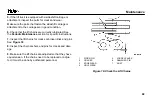
Страница 59: ...Figure 13 Maintenance Points MRW020 030 E Figure 14 Maintenance Points MCS025 030 040 E Maintenance Schedule 57...
Страница 60: ...Figure 15 Maintenance Points MSW025 030 F Maintenance Schedule 58...
Страница 81: ...Figure 23 Remove Install Battery From Battery Power Pack Maintenance 79...
Страница 92: ...A TOP VIEW B LEFT VIEW 1 DRIVE END 2 FORK END 3 STRAP Figure 24 Lifting Points Maintenance 90...
Страница 93: ...Figure 25 Putting the Lift Truck on Blocks MSW MRW Shown Maintenance 91...
Страница 96: ...A TOP VIEW B LEFT VIEW 1 STRAP 2 ANCHOR POINT Figure 26 Lift Truck Tie Downs Maintenance 94...
Страница 97: ...Spacer 7 18 5 18 11 17 8 16 1 16 7 14 2 13 9 09 9 08 3 08...


