13
The brake unit is, in part, disassembled as described in 2.).
After removing the circlip (52) the pressure plate (51) can be
removed from the air brake piston (49) this, in turn, can now
be removed from the air brake housing (46). If the exchange
valve function in the brake housing (40) is defect release the
spacer screws ( 42) and remove the control piston (41).
Reassemble
In the main reassemble is performed in the reverse order to
disassembly.
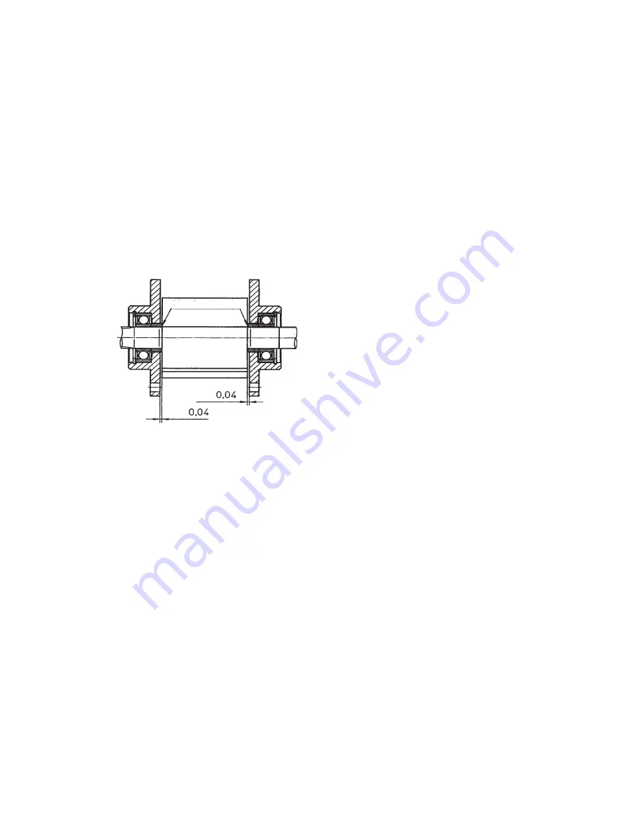
Pay attention to the motor clearances.
The axial play between the rotor (12) and the seal plates
(5 and 20) should be around 0.04 mm
The broken edges on the spacer rings (8 and 23) must face
in toward the middle of the rotor
Before replacing the vanes (17) clean the rotor slots from oil
and resin residues. The new vanes must move freely in the
rotor slots (12). Grease the bearings (6 and 21).
ATTENTION
: If the bearings (6 and 21) have been renewed
the clearances must be readjusted (see drawing above).
Ensure that the bearing inner race is pressed, without play,
against the circlip to set the spacer ring (8 and 23) clearances
(new spacer rings must always be adapted). After fitting the
motor cover (25) the rotor (12) must rotate freely. If the rotor
is hard to rotate or does not rotate at all it can be helpful to
apply light taps with a rubber hammer to the motor housing
(1, to the side or axially) to seat the rotor (12) and remove
tensions. Replace the oil seal (31) and seal plate (30). Take
care not to damage the sealing lips! Position the O-Ring
(29) and replace the brake housing (40) complete with
change valve. Remember to position O-Ring (43).
Apply antirust paste as described above (to rotor splines
(12), brake housing (40) and brake disc (44)). Replace brake
disc and ensure it moves freely. Pre-assemble air brake
piston and (49) and pressure plate (51) into the air brake
housing. Coat all moving faces with antirust paste. Replace
the brake housing assembly (40). Enter the springs (53).
Centre the brake housing cover (54) and secure with screws
(55). Replace motor cover (32) and secure with screws (33).
Replace the air control valve and check all motor functions.
Due to the asymmetric design of the hoist the running noises
and idle speeds for RH and LH rotation differ. The values
quoted in the table on page 7 always refer to the pull/lifting
side. Test the brake open and hold open functions when air
is applied. To prevent a continual slipping of the brake linings
a pressure of at least 2.6 bar must be applied.
Broken edges
Around
Around
Содержание CPA Series
Страница 1: ...1 ModelCPA OperatingandServiceInstructions SparePartsList Issue January 2002...
Страница 18: ...18 Fig 19 Gearbox...
Страница 28: ...28 Fig 29 Air motor for trolley...


