VL-1000 Technical Supplement
Alignment
VR1002: Reverse ALC (Slight power turn-down into 75
Ω
dummy load)
VR1001: Forward ALC (High Power)
(PO=1000 W on AVG PWR meter)
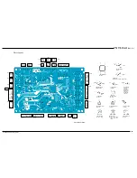
CNTL Unit Alignment Points
power are obtained, the FT-920 transceiver’s ALC
meter should have
six bars
illuminated. Other
transceivers should show mid-scale indication on
their ALC meter.
Ì
Unkey the transmitter when adjustment is suc-
cessful. Now press and hold in the
INPUT
switch
on the VL-1000 front panel for ½ second to exit
the ALC alignment mode.
Ì
If your VL-1000 is after prod. lot 002, key the
transmitter with the
DRIVE
or
RF PWR
con-
trol fully clockwise, adjust VR2001 for 1000 Watts
on the
AVG PWR
meter.
Forward ALC Adjustment (Low Power)
Ì
The transceiver should be left at 50.100 MHz in
the FM mode, with the transceiver’s
DRIVE
or
RF PWR
control fully clockwise.
Ì
Press the
LOW
switch on the front panel of the
VL-1000. Now press and hold in the
INPUT
switch for ½ second so as to enter the “ALC Align-
ment” mode once again.
Ì
Key the transmitter, and press the
DISPLAY 1
(to increase the power) or the
DISPLAY 2
key
(to decrease the power) so as to achieve 500
Watts output power as displayed on the
AVG
PWR
meter.
Ì
Return the transceiver to the receive mode. Press
and hold in the
INPUT
switch for ½ second to
exit the ALC Alignment mode.
Reverse ALC Adjustment
Ì
Press the
ANT
switch on the front panel to select
ANTENNA 2
(to which the 75
Ω
dummy load is
connected).
Ì
With the transceiver still set to 50.100 MHz in
the FM mode, set the
DRIVE
or
RF PWR
con-
trol of the transceiver fully clockwise. If neces-
sary, press the
LOW
switch to select
high power
operation.
Ì
Press and hold in the
INPUT
switch for ½ sec-
ond to enter the “ALC Alignment” mode.
Содержание VL-1000
Страница 8: ...VL 1000 Technical Supplement Chip Component Information Notes...
Страница 11: ......
Страница 12: ......
Страница 13: ......
Страница 14: ......
Страница 20: ...VL 1000 Technical Supplement Alignment Notes...
Страница 21: ...VL 1000 Technical Supplement Block Diagram...
Страница 22: ...VL 1000 Technical Supplement Interconnection Diagram...
Страница 24: ...VL 1000 Technical Supplement CNTL Unit Notes...
Страница 26: ...VL 1000 Technical Supplement CNTL Unit Chip Side...
Страница 27: ...VL 1000 Technical Supplement CNTL Unit Lot 2 Circuit Diagram...
Страница 28: ...VL 1000 Technical Supplement CNTL Unit Lot 2 Notes...
Страница 30: ...VL 1000 Technical Supplement CNTL Unit Lot 2 Chip Side...
Страница 37: ...VL 1000 Technical Supplement Tuner Unit Circuit Diagram...
Страница 38: ...VL 1000 Technical Supplement Tuner Unit Notes...
Страница 40: ...VL 1000 Technical Supplement Tuner Unit Chip Side...
Страница 41: ...VL 1000 Technical Supplement Circuit Diagram Tuner Unit Lot 4...
Страница 42: ...VL 1000 Technical Supplement Notes Tuner Unit Lot 4...
Страница 44: ...VL 1000 Technical Supplement Chip Side Tuner Unit Lot 4...
Страница 46: ...VL 1000 Technical Supplement Chip Side Tuner Unit Lot 7...
Страница 50: ...VL 1000 Technical Supplement Tuner Unit Notes...
Страница 51: ...VL 1000 Technical Supplement LPF Unit Circuit Diagram...
Страница 52: ...VL 1000 Technical Supplement LPF Unit Notes...
Страница 54: ...VL 1000 Technical Supplement LPF Unit Solder Side...
Страница 55: ...VL 1000 Technical Supplement LPF Unit Lot 4 Circuit Diagram...
Страница 56: ...VL 1000 Technical Supplement LPF Unit Lot 4 Notes...
Страница 58: ...VL 1000 Technical Supplement LPF Unit Lot 4 Solder Side...
Страница 63: ...VL 1000 Technical Supplement Divider Unit Circuit Diagram...
Страница 64: ...VL 1000 Technical Supplement Divider Unit Notes...
Страница 66: ...VL 1000 Technical Supplement Divider Unit Solder Side...
Страница 67: ...VL 1000 Technical Supplement Circuit Diagram Divider Unit Lot 3...
Страница 68: ...VL 1000 Technical Supplement Divider Unit Lot 3 Notes...
Страница 70: ...VL 1000 Technical Supplement Solder Side Divider Unit Lot 3...
Страница 74: ...VL 1000 Technical Supplement PA Unit Notes...
Страница 76: ...VL 1000 Technical Supplement PA Unit Solder Side...
Страница 77: ...VL 1000 Technical Supplement PA Unit Lot 5 Circuit Diagram...
Страница 78: ...VL 1000 Technical Supplement PA Unit Lot 5 Notes...
Страница 80: ...VL 1000 Technical Supplement PA Unit Lot 5 Solder Side...
Страница 84: ...VL 1000 Technical Supplement PA Unit Notes...
Страница 85: ...VL 1000 Technical Supplement Display Unit Circuit Diagram...
Страница 86: ...VL 1000 Technical Supplement Display Unit Notes...
Страница 92: ...VL 1000 Technical Supplement Display Unit Notes...
Страница 93: ...VL 1000 Technical Supplement ANT SW Unit Circuit Diagram...
Страница 94: ...VL 1000 Technical Supplement ANT SW Unit Notes...
Страница 99: ...VL 1000 Technical Supplement Line Filter Unit Circuit Diagram...
Страница 100: ...VL 1000 Technical Supplement Line Filter Unit Notes...
Страница 102: ...VL 1000 Technical Supplement Line Filter Unit Notes...
Страница 108: ...VL 1000 Technical Supplement Jack Unit Parts List REF DESCRIPTION VALUE WV TOL LAY ADR YAESU P N MFGR S DESIG VERS LOT...
Страница 110: ...VL 1000 Technical Supplement Relay Unit Notes...
Страница 112: ...VL 1000 Technical Supplement Filter Unit AC Power Supply VP 1000 Notes...
Страница 114: ...VL 1000 Technical Supplement Filter Unit AC Power Supply VP 1000 Notes...
Страница 115: ......
Страница 116: ......
Страница 117: ......
Страница 118: ......
Страница 119: ......
Страница 120: ......
Страница 121: ......
Страница 122: ......
Страница 123: ......
Страница 124: ......
Страница 125: ......
Страница 126: ......
Страница 127: ......
Страница 128: ......
Страница 129: ......
Страница 130: ......
Страница 131: ......


