


VL-1000 Technical Supplement
Alignment
Read each step to determine if the same test
equipment used in the
previous
step will be required.
If not,
remove
the test equipment (except the Dum-
my Load and Wattmeter) before proceeding.
The in-line Wattmeter is not used for any specif-
ic alignment procedure. However, it is extremely
useful for the purpose of verifying proper signal
flow from the rear panel antenna jacks.
Correct alignment requires that the ambient tem-
perature of the VL-1000, the exciter, and the test equip-
ment all be the same, and that this temperature should
be between 20° and 30° C (68° ~ 86° F). If any equip-
ment is brought into the shop from an environment
that is hotter or colder than this temperature range, it
should be allowed time for thermal equalization be-
fore alignment is begun.
Amplifier alignment must only be performed
with all circuit boards firmly in place. All voltages
shown in alignment procedures are nominal (±10%
tolerance).
PA Unit Idling Current
The adjustment of the PA Idling Current must
be performed twice, as there are two identical 500W
PA Units in the VL-1000. When performing align-
ment steps, be certain that you confine your work
to one PA Unit at a time.
Ì
With the transceiver, power supply, and ampli-
fier all turned off, connect all interconnection
cables required for normal operation. Connect
the DC Ammeter in the +48-Volt line between
the VL-1000 and VP-1000.
Ì
With the front panel of the VL-1000 facing to-
ward you, align the PA Unit on the
left
side of
the amplifier (immediately behind the left fan)
first
; after completing this alignment, repeat the
process on the
right
PA Unit, as instructed be-
low.
Ì
Disconnect the wires connected to J5001 and
J5007 of the
right
PA Unit, and move them safe-
ly out of the way.
Ì
Turn on the power supply, amplifier, and trans-
ceiver. Preset VR5001, VR5002, VR5003 and
VR5004 on the
left
PA Unit fully counterclock-
wise. Key the transmitter in the SSB mode (with
zero
drive power), and adjust VR5003 for 210 mA,
VR5004 for 400 mA,VR5001 for 610 mA, and
VR5002 for 800 mA on the DC Ammeter. Try to
make these adjustments in order, and as quick-
ly as possible. When done, turn off the power
supply, amplifier, and transceiver.
Ì
Now remove both +48V wires (one each from
J5001 and J5007) from the
left
PA Unit.
Ì
The next steps will be performed on the
right
PA
Unit.
Ì
Connect both +48V wires (one each to J5001 and
J5007) on the
right
PA Unit. Turn on the power
supply, amplifier, and transceiver. Preset
VR5001, VR5002, VR5003 and VR5004 on the
right
PA Unit fully counterclockwise. Key the
transmitter in the SSB mode (with
zero
drive
power), and adjust VR5003 for 210 mA, VR5004
for 400 mA,VR5001 for 610 mA, and VR5002
for 800 mA on the DC Ammeter. Try to make
these adjustments in order, and as quickly as
possible.
Ì
Now connect both +48V wires (one each to J5001
and J5007) on the
left
PA Unit. All +48V wires
should now be connected on both PA Units.
Содержание VL-1000
Страница 8: ...VL 1000 Technical Supplement Chip Component Information Notes...
Страница 11: ......
Страница 12: ......
Страница 13: ......
Страница 14: ......
Страница 20: ...VL 1000 Technical Supplement Alignment Notes...
Страница 21: ...VL 1000 Technical Supplement Block Diagram...
Страница 22: ...VL 1000 Technical Supplement Interconnection Diagram...
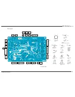
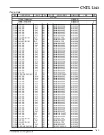
Страница 24: ...VL 1000 Technical Supplement CNTL Unit Notes...
Страница 26: ...VL 1000 Technical Supplement CNTL Unit Chip Side...
Страница 27: ...VL 1000 Technical Supplement CNTL Unit Lot 2 Circuit Diagram...
Страница 28: ...VL 1000 Technical Supplement CNTL Unit Lot 2 Notes...
Страница 30: ...VL 1000 Technical Supplement CNTL Unit Lot 2 Chip Side...
Страница 37: ...VL 1000 Technical Supplement Tuner Unit Circuit Diagram...
Страница 38: ...VL 1000 Technical Supplement Tuner Unit Notes...
Страница 40: ...VL 1000 Technical Supplement Tuner Unit Chip Side...
Страница 41: ...VL 1000 Technical Supplement Circuit Diagram Tuner Unit Lot 4...
Страница 42: ...VL 1000 Technical Supplement Notes Tuner Unit Lot 4...
Страница 44: ...VL 1000 Technical Supplement Chip Side Tuner Unit Lot 4...
Страница 46: ...VL 1000 Technical Supplement Chip Side Tuner Unit Lot 7...
Страница 50: ...VL 1000 Technical Supplement Tuner Unit Notes...
Страница 51: ...VL 1000 Technical Supplement LPF Unit Circuit Diagram...
Страница 52: ...VL 1000 Technical Supplement LPF Unit Notes...
Страница 54: ...VL 1000 Technical Supplement LPF Unit Solder Side...
Страница 55: ...VL 1000 Technical Supplement LPF Unit Lot 4 Circuit Diagram...
Страница 56: ...VL 1000 Technical Supplement LPF Unit Lot 4 Notes...
Страница 58: ...VL 1000 Technical Supplement LPF Unit Lot 4 Solder Side...
Страница 63: ...VL 1000 Technical Supplement Divider Unit Circuit Diagram...
Страница 64: ...VL 1000 Technical Supplement Divider Unit Notes...
Страница 66: ...VL 1000 Technical Supplement Divider Unit Solder Side...
Страница 67: ...VL 1000 Technical Supplement Circuit Diagram Divider Unit Lot 3...
Страница 68: ...VL 1000 Technical Supplement Divider Unit Lot 3 Notes...
Страница 70: ...VL 1000 Technical Supplement Solder Side Divider Unit Lot 3...
Страница 74: ...VL 1000 Technical Supplement PA Unit Notes...
Страница 76: ...VL 1000 Technical Supplement PA Unit Solder Side...
Страница 77: ...VL 1000 Technical Supplement PA Unit Lot 5 Circuit Diagram...
Страница 78: ...VL 1000 Technical Supplement PA Unit Lot 5 Notes...
Страница 80: ...VL 1000 Technical Supplement PA Unit Lot 5 Solder Side...
Страница 84: ...VL 1000 Technical Supplement PA Unit Notes...
Страница 85: ...VL 1000 Technical Supplement Display Unit Circuit Diagram...
Страница 86: ...VL 1000 Technical Supplement Display Unit Notes...
Страница 92: ...VL 1000 Technical Supplement Display Unit Notes...
Страница 93: ...VL 1000 Technical Supplement ANT SW Unit Circuit Diagram...
Страница 94: ...VL 1000 Technical Supplement ANT SW Unit Notes...
Страница 99: ...VL 1000 Technical Supplement Line Filter Unit Circuit Diagram...
Страница 100: ...VL 1000 Technical Supplement Line Filter Unit Notes...
Страница 102: ...VL 1000 Technical Supplement Line Filter Unit Notes...
Страница 108: ...VL 1000 Technical Supplement Jack Unit Parts List REF DESCRIPTION VALUE WV TOL LAY ADR YAESU P N MFGR S DESIG VERS LOT...
Страница 110: ...VL 1000 Technical Supplement Relay Unit Notes...
Страница 112: ...VL 1000 Technical Supplement Filter Unit AC Power Supply VP 1000 Notes...
Страница 114: ...VL 1000 Technical Supplement Filter Unit AC Power Supply VP 1000 Notes...
Страница 115: ......
Страница 116: ......
Страница 117: ......
Страница 118: ......
Страница 119: ......
Страница 120: ......
Страница 121: ......
Страница 122: ......
Страница 123: ......
Страница 124: ......
Страница 125: ......
Страница 126: ......
Страница 127: ......
Страница 128: ......
Страница 129: ......
Страница 130: ......
Страница 131: ......


