background image

PCC-2000


R

EFERENCE

 B

OOK

- 9 -

RF G

AIN

 C

ONTROL

M

AIN

 B

AND


(

VFO-A

)

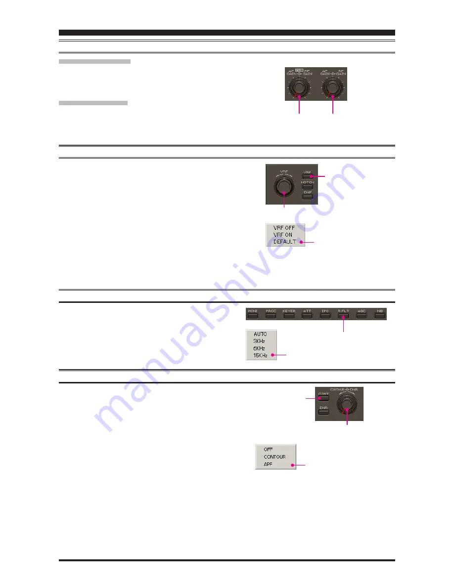
Click the left mouse button on the main [

RF GAIN

] knob (the

indication color of “RF GAIN” will turn yellow), then turn the
mouse scroll or press the left/right buttons to adjust the RF gain.

S

UB

 B

AND


(

VFO-B

)

Click the left mouse button on the sub [

RF GAIN

] knob (the

indication color of “RF GAIN” will turn yellow), then turn the
mouse scroll or press the left/right buttons to adjust the RF gain.

VRF 

(

V

ARIABLE

 RF F

RONT

-

END

 F

ILTER

)

 O

PERATION

1. Click the left mouse button on the [

VRF

] button to open the

“VRF” pop-up window, then select the configuration you wish
to use.

VRF OFF

: Turns the VRF filter off.

VRF ON

: Turns the VRF filter on.

DEFAULT

: Moves the passband of the VRF filter to the cen-

ter of the current amateur band.

2. When you have set the [

VRF

] button to “VRF ON:”

ˆ

Bring the mouse cursor to the [

VRF

] knob, then turn the

mouse scroll to move the passband of the VRF filter.

ˆ

Press and hold in the left mouse button on the edge of the
[

VRF

] knob, then rotate the mouse to move the passband

of the VRF filter while holding the left mouse button.

R

OOFING

 F

ILTER

 S

ELECTION

Click the left mouse button on the [

R.FLT

] button to open the

“Roofing Filter” pop-up window, then select the bandwidth you
wish to utilize.

CONTOUR F

ILTER

 / APF 

(

A

UDIO

 P

EAK

 F

ILTER

)

 O

PERATION

1. Click the left mouse button on the [

CONT

] button to open

the “Contour/APF” pop-up window, then select the configu-
ration you wish to use.

OFF

:

Turns the Contour filter/APF both off.

CONTOUR

: Turns the Contour filter on. The Contour filter

characteristic will appear in the display

APF

:

Turns the APF (Audio Peak Filter) filter on.
The APF is activated only with a CW mode.
The “CONTOUR” indication on the display
will change to “APF”.

2. When the Contour filter is set to on, click the left mouse but-

ton on the edge of the [

CONTOUR

] knob (the indication

color of “CONTOUR” will turn yellow), then turn the mouse
scroll or press the left/right buttons to adjust the center fre-
quency of the Contour filter 

(There is no adjustmet knob as-

sociated with the APF)

.

Main [

RF GAIN

] knob

Sub [

RF GAIN

] knob

[

VRF

] knob

[

VRF

] button

“VRF” window

[

R.FLT

] button

“R.FLT” window

[

CONTOUR

] knob

[

CONT

] button

“Contour/APF” window

Содержание PCC-2000

Страница 1: ...he Software in such situations All title and copyrights in and to the Software including but not limited to any data images text and other components and the accompanying printed materials are owned b...

Страница 2: ...Noise Reduction Operation 10 NAR One Touch Narrow IF Filter Selection 11 Noise Blanker Operation 11 AGC 12 LOCK Feature 12 VOX Operation 12 Using the Speech Processor 13 Using the Monitor 13 Antenna T...

Страница 3: ...ce 256 MB or more RAM RS 232C port 1024 x 768 color display with 256 bit color support on the video card RS 232C Straight Cable DB9 pin Female to DB9 pin Female Or USB to RS 232C Adapter Cable SomeUSB...

Страница 4: ...tton of the PCC 2000 Personal Computer Controller to turn the transceiver On and Off Note the transceiver s rear panel Power switch must already have been turned on manually AF GAIN CONTROL MAIN BAND...

Страница 5: ...e Main Band VFO A frequency The frequency digit will change to Orange 2 Turn the mouse scroll to tune the frequency digit of the Main Band VFO A frequency BAND CHANGE Click the left mouse button on th...

Страница 6: ...equency The frequency digit will change to Orange 2 Turn the mouse scroll to tune the frequency digit of the Sub Band VFO B frequency BAND CHANGE Click the left mouse button on the B button then click...

Страница 7: ...set frequency thereby setting the offset to Zero CLAR KNOB Click the left mouse button on the CLAR knob then turn the mouse scroll to tune the Clarifier offset frequency Press and hold in the left mou...

Страница 8: ...on the STOP button for the Voice Memory feature to stop the playback ANTENNA SELECTION Click the left mouse button on the ANTENNA 1 2 button to open the ANT pop up window then select the antenna on wh...

Страница 9: ...b then rotate the mouse to move the passband of the VRF filter while holding the left mouse button ROOFING FILTER SELECTION Click the left mouse button on the R FLT button to open the Roofing Filter p...

Страница 10: ...form coarse adjustment of the center frequency of the IF Notch filter 3 Click the left mouse button on the edge of the FINE knob the indication color of FINE will turn yellow then turn the mouse scrol...

Страница 11: ...ish to use NB OFF Turns the Noise Blanker off NB ON Turns the Noise Blanker on for short duration pulses NB W ON Turns the Noise Blanker on for longer duration pulses 2 When you have set the NB button...

Страница 12: ...ing Dial knob is set to be locked the LOCK icon will ap pear in the display VOX OPERATION 1 Click the left mouse button on the VOX button to turn the VOX circuit on and off When the VOX circuit is set...

Страница 13: ...roll or press the left right buttons to select the Compression level USING THE MONITOR 1 Click the left mouse button on the MONI button to turn the Monitor circuit on and off When the Monitor is set t...

Страница 14: ...pen the CTCSS Tone Frequency pop up window and then select the desired tone frequency 4 Click the OK button to close the CTCSS Tone Frequency pop up window 5 Click the left mouse button on the S or bu...

Страница 15: ...ophone equalizer Green Curve Appears the characteristic of the high range for the parametric microphone equalizer Black Curve Appears the characteristic of the overall range for the parametric microph...

Страница 16: ...o adjusts the equalizer gain of the middle range of the parametric microphone equalizer Available selections are 20 dB 10 dB h PRMTRC EQ2 P PRMTRC EQ2 BWTH Click the left mouse button on the but ton t...

Страница 17: ...eft mouse button on the desired Memory Channel button Message Play Ch 1 Message Play Ch 5 or Text Play Ch 1 Text Play Ch 5 to begin playback of the recorded audio ROTATOR CONTROL 1 Click the left mous...

Страница 18: ...k the left mouse button on the DIM button to toggle the illumination level of the Meter Display between Hi and Low MOX BUTTON Click the left mouse button on the MOX button to engage trans mission When...

Страница 19: ...button on the Main RX button to toggle the Main Band VFO A receiver on and off When the Main Band VFO A receiver is set to on the button glows green MAIN TX BUTTON Click the left mouse button on the...

Страница 20: ...M button to copy the current operating data from the Main band VFO A into the currently selected memory channel overwriting any previous data stored there MAIN VFO A BAND BUTTON Clicking the left mous...

Страница 21: ...reases the tuning rate of the SUB VFO B knob by a factor of 10 A B BUTTON Click the left mouse button on the A B button to toggle the actions of the SUB VFO B button between the Main band VFO A and Su...

Страница 22: ...enu item you wish to work on then double click the left mouse button on the Menu item to open the pop up window 3 Change the current setting of the selected Menu item then click the OK button to close...

Страница 23: ...mmand Send pop up window 2 Enter the CAT command you wish send to the FT 2000 with the PC keyboard For example Set the VFO A frequency to 14 250000 MHz FA14250000 Refer to a FT 2000 CAT Operation Refe...

Страница 24: ...key Example 1 Set the VFO A frequency to 14 250000 MHz FA14250000 Example 2 Set the VFO A Operating Mode to USB MD02 Example 3 Set the VFO A frequecy to 14 250000 MHz USB mode FA14250000 MD02 Notice i...

Страница 25: ...PCC 2000 REFERENCE BOOK 25 NOTE...

Страница 26: ...PCC 2000 REFERENCE BOOK Copyright 2009 VERTEX STANDARD CO LTD All rights reserved No portion of this manual may be reproduced without the permission of VERTEX STANDARD CO LTD...

Отзывы: