background image

21

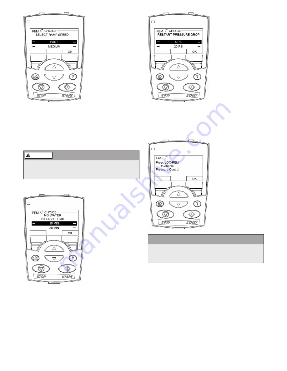
RAMP SPEED 

SETTING:

 Select 

the ramp speed 
based on the system 
requirements. The 
ramp speed sets the 
acceleration and 
deceleration time 
for the motor. The 
acceleration time 
is the time for the 
motor to transition 
from 0Hz (stopped) 
to 60Hz (full speed). 
The deceleration time 
is the time for the 
motor to transition 

from 60Hz (full speed) to 0Hz (full stopped). The 
FAST ramp selection sets the acceleration ramp to 5 
seconds and the deceleration ramp to 8 seconds.  The 
MEDIUM ramp selection sets both the acceleration 
and the deceleration ramp to 25 seconds. The SLOW 
ramp selection sets both the acceleration and the 
deceleration ramp to 60 seconds.

Setting the Ramp Speed too fast can result in 
unstable operation and can damage pump, motor 
and piping.

NO WATER RESTART 

TIME SETTING:

 The 

No Water Restart 
Setting sets the time 
between detection 
of a No Water/Loss 
of Prime fault and the 
restart of the system. 
For example, if the No 
Water Restart Time 
is set to 10 MIN, the 
system will restart 10 
minutes after a Water/
Loss of Prime fault has 
been detected. This 
parameter is typically 
set according to the 

recovery rate of the water source. The restart time can 
be set to 10 minutes, 30 minutes or 1 hour using the 
Start-Up Assistant. 

RESTART PRESSURE 

DROP SETTING:

 The 

Restart Pressure Drop 
Setting allows the user 
to select the amount of 
pressure drop allowed 
in the system before 
the pump restarts after 
a No Water Demand 
condition is detected. 
A No Water Demand 
condition exists 
when the pump has 
satisfied the desired 
system pressure and 
reached the minimum 
frequency. If the 

Restart Pressure Drop is set to 5 PSI and the pump has 
satisfied the desired system pressure and turned off 
on no demand, the controller will turn the pump back 
on after the system pressure has dropped 5 PSI below 
the system pressure setting.

START REMINDER 

SCREEN:

 This is a 

reminder screen. 
This screen is shown 
only if the controller 
is set to local mode 
(LOC). To change to 
remote mode (REM) 
and enable pressure 
control, press the LOC/
REM button.

CAUTION
The controller ignores the pressure sensor feedback 
signal and Start Signal on DI1 when operated in local 
(LOC) mode. Hazardous pressure can result.

The controller is now set up and is ready to be started.

SETTING THE CONTROL MODE
The Control Mode can be set to either local (LOC) 
or remote (REM). The Control Mode is indicated in 
the upper left hand corner of the display screen. Use 
REM for pressure control mode. This mode uses the 
pressure transducer feedback on AI2 to control the 
system pressure. Note that the start and stop buttons 
on the display are disabled in REM mode. The start 
enable on DI1 can be used to remotely start and stop 
the motor. Use LOC for fixed speed mode. The speed 
can be set with the up and down buttons on the 
keypad. The motor can be started and stopped using 
the start and stop buttons on the keypad. The in LOC 
mode the start enable on DI1 is disabled.

WARNING

Содержание CentriPro SPD Plus

Страница 1: ... C US Models Covered SPD Plus 230V 1Ø Input 20 30 HP 230V 3Ø Input 40 60 HP 460V 40 100 HP 575V 40 100 HP SPD Plus VARIABLE SPEED PUMP CONTROL INSTALLATION AND OPERATION MANUAL INSTRUCTION MANUAL IM244R04 ...

Страница 2: ...____________ Unpack the Drive NOTE Lift the SPD PLUS by its chassis and not by its cover 1 Unpack the drive 2 Check for any damage and notify the shipper immediately if damaged com ponents are found 3 Check the contents against the order and the shipping label to verify that all parts have been received Prepare the Mounting Location The drive requires a smooth vertical solid surface free from heat...

Страница 3: ...l terminals are wired and tightened as specified NO tools or foreign objects such as drill shavings are inside the drive NO alternate power source for the motor is connected no input voltage is applied to the output of the drive 5 3 1 DIR MENU REM 11 1 LOC REM 40 2 PSI sp 0 0 PSI ac 0 0 HZ Reinstall the Cover 1 Align the cover and slide it on 2 Tighten the captive screw 3 Reinstall the control pan...

Страница 4: ...x B Fuse and Wire Sizing 29 31 Appendix C Weights and Dimensions 31 Limited Warranty 36 NOTE Input and Output power connections require a minimum of 75ºC rated Copper wire only In order to maintain the environmental rating integrity of the enclosure all openings must be closed by equipment rated Type 1 for Type 1 enclosures or Type 3R for Type 3R enclosures Maximum Ambient temperature range 5º F 1...

Страница 5: ...MUST be disconnected from the main power supply before attempting any operation or main tenance on the electrical or mechanical part of the system Failure to disconnect electrical power before attempting any operation or maintenance can result in electrical shock burns or death 6 When in operation the motor and pump could start unexpectedly and cause serious injury 7 Even when the motor is stopped...

Страница 6: ...EC or the Canadian Electrical Code CEC as well as all local state and provincial codes Code questions should be directed to your local electrical inspector or code enforcement agency Failure to follow electrical codes and OSHA safety standards may result in personal injury or equipment damage Failure to follow manufacturer s installation instructions may result in electrical shock fire hazard pers...

Страница 7: ...600N1 60 30 160 80 178 89 R6 460 SPD40400 40 53 59 N4 SPD40400F 40 65 72 N4 SPD40400N1 40 53 59 R4 SPD40500 50 65 72 N4 SPD40500F 50 87 97 N5 SPD40500N1 50 65 72 R4 SPD40600 60 87 97 N5 SPD40600F 60 87 97 N5 SPD40600N1 60 87 97 R4 SPD40750 75 113 125 N6 SPD40750F 75 113 125 N6 SPD40750N1 75 113 125 R5 SPD41000 100 141 157 N6 SPD41000F 100 141 157 N6 SPD41000N1 100 141 157 R6 575 SPD50400N1 40 47 5...

Страница 8: ... a submersible pump and control system 3 FLOW 4 6 5 1 2 8 9 7 U1 V1 W1 GND U2 V2 W2 GND 10 11 NOTE The SPD Plus is not recommended for the residential well applications Consult CentriPro for suitable Variable Speed Controllers designed for residential well pumps NOTE Systems MUST be designed by qualified technicians only and meet all applicable state and local code requirements SUPPLY POWER 1 DRIV...

Страница 9: ...the SPD Plus can create dangerous pressure Select pipe and fittings according to your pipe suppliers recommendation Consult local codes for piping requirements in your area All joints must be airtight Use PTFE thread seal tape or another type of pipe sealant to seal threaded connections Please be careful when using thread sealant as any excess that gets inside the pipe may plug the pressure sensor...

Страница 10: ...anted transient voltages and noise into the system Do not run the pressure sensor cable alongside the input or output wiring for more than 1 foot Maintain a distance of at least 8 between the pressure sensor cable and input or output wiring Hazardous Pressure CAUTION Ensure the pressure sensor cable is connected as follows Brown to terminal 10 24VDC SUPPLY White to terminal 5 AI2 TRANSDUCER FEEDBA...

Страница 11: ...G If the secondary of the transformer is a delta with a grounded leg corner grounded delta or floating network the line to ground EMC filter components and line to ground MOV protection must be disconnected or damage to the controller can result Remove screws EM1 and EM3 for frame sizes R4 N4 to disable line to ground EMC filter and MOV protection WARNING Hazardous voltage ...

Страница 12: ... delta with a grounded leg corner grounded delta or floating network the line to ground EMC filter components and line to ground MOV protection must be disconnected or damage to the controller can result Remove screws F1 and F2 for frame sizes R5 N5 and R6 N6 to disable line to ground EMC filter and MOV protection NOTE For single phase input power use input power terminals U1 W1 and PE ground WARN...

Страница 13: ...tart and stop the drive while in REM mode replace the jumper wire with a non powered switch Identification RELAY OUTPUTS R04 TO R06 1 RO4C 2 RO4A Relay output 3 RO4B Default operation Started 4 RO5C 5 RO5A Relay output 6 RO5B Default operation Running 7 RO6C 8 RO6A Relay output 9 RO6B Default operation Fault FIGURE 4 NOTE Pressure sensor cable must be wired during installation All other connection...

Страница 14: ... and MOV protection Refer to Figures 1 2 and 3 for screw locations UNGROUNDED SECONDARY Grounding of the transformer secondary is essential to the safety of personnel as well as the safe operation of the drive Leaving the secondary floating can permit dangerously high voltages between the chassis of the drive and the internal power structure components In many cases this voltage could exceed the r...

Страница 15: ...NE three phase six winding transformer A delta primary is best for third harmonic cancellation A wye secondary avoids circulating current problems and provides the very desirable option of grounding the secondary neutral for minimum voltage stress and ripple to ground The transformer should have a KVA rating at least 1 1 times the maximum connected HP A K factor of 6 is sufficient if transformer i...

Страница 16: ...nd 3 for details Ensure the ground wire is connected back to the service entrance ground and that the service entrance ground is bonded to a proper ground rod Ensure disconnect switches are locked in the OFF position before making this connection For models with an N1 NEMA 1 suffix connect conduit to the conduit box supplied with the controller For all other models NEMA 3R drill a hole that is pro...

Страница 17: ... and N6 it may be necessary to drill a hole in the bottom of the enclosure for conduit and wire entry Consult motor manual to determine the wire size for the application Ensure the ground connection to the motor is continuous Connect wires to the output terminal block on the controller labeled U2 V2 W2 and GND Connect the ground wire to the terminal labeled GND If a reactor is used for a submersib...

Страница 18: ...d to implement this function WARNING Disabling the Start Ramp function by removing the prewired connections can result in damage to the submersible motor and will void the motor and controller warranty No Water Restart Time The No Water Restart Time is used to automatically restart the controller after a No Water Loss of Prime dry well Fault is detected This function is implemented using DI2 14 Fa...

Страница 19: ...h the up and down buttons In remote mode REM the drive uses the pressure sensor feedback signal to control the system pressure Reference Value In REM Displays the pressure setting in In LOC Displays the speed reference in Hz Pressure Setpoint Displays the system pressure setpoint in PSI Actual System Pressure Displays the actual system pressure in PSI as indicated by the pressure transducer Motor ...

Страница 20: ... screens are shown below MOTOR TYPE SETTING Select the motor type used in the application using the up and down arrows and press OK The minimum frequency is set to 30Hz for the Submersible setting and 15Hz for the Above Ground setting The next prompt will be for either to enter the motor horsepower rating or the motor nominal current rating The prompt displayed will depend on the controller size M...

Страница 21: ... in the system before the pump restarts after a No Water Demand condition is detected A No Water Demand condition exists when the pump has satisfied the desired system pressure and reached the minimum frequency If the Restart Pressure Drop is set to 5 PSI and the pump has satisfied the desired system pressure and turned off on no demand the controller will turn the pump back on after the system pr...

Страница 22: ... give the correct rotation NOTE It is possible for the pump to maintain constant pressure with a low flow or a high suction head even if the pump is rotating backwards While the pump is running use an amp probe on one of the output power leads connected to the motor and compare the current draw between the two rotation directions The lowest current reading typically indicates the pump is running i...

Страница 23: ... keypad NOTE It may be necessary to remove and reapply the Start Signal on DI1 to start the drive after a fault is reset by pressing RESET on the keypad Turn the power off for 5 minutes then turn on Fault Code Fault Name In Panel Description and Recommended Corrective Action 1 OVERCURRENT Output current is excessive Check for and correct Excessive motor load pump overload Insufficient acceleration...

Страница 24: ...ad from the meter to the White wire in the sensor cable The meter will display the output of the sensor If functioning properly the output of the sensor will be between 4mA and 20mA depending on the pressure in the system Refer to the chart below to determine the sensor feedback at various pressures NOTE The controller is programmed to automatically reset the Transducer Loss Fault every 10 seconds...

Страница 25: ... 26 DRIVE ID Internal fault Configuration Block Drive ID is not valid Contact factory 27 CONFIG FILE Internal configuration file has an error Contact factory 34 MOTOR PHASE Fault in the motor circuit One of the motor phases is lost Check for and correct Motor fault Motor cable fault Internal fault 35 OUTP WIRING Possible power wiring error detected When drive is not running it monitors for an impr...

Страница 26: ...h other Ensure at least 8 between power wires and all other wiring 2008 PANEL LOSS Panel communication is lost and the drive is in local control mode LOC Check for and correct Communication lines and connections 2009 DEVICE OVERTEMP Drive heatsink is hot This alarm warns that a DEVICE OVERTEMP fault may be near Check for and correct Fan failure Obstructions in the air flow Dirt or dust coating on ...

Страница 27: ...n Specifications 208 220 230 240 VAC 3 phase or 1 phase 15 10 for SPD2XXXX Voltage U1 380 400 415 440 460 480 VAC 3 phase 15 10 for SPD4XXXX 500 525 575 600 VAC 3 phase 15 10 for SPD5XXXX Prospective Short Maximum allowed prospective short circuit current in the supply is 100 kA Circuit Current providing that the input power cable of the drive is protected with IEC 629 appropriate fuses US 100 000...

Страница 28: ...ounded TN systems are defined in the following table In such systems disconnect the internal ground connection through the EMC filter capacitors do this also if the grounding configuration of the system is unknown see SECTION 6 POWER SUPPLY AND WIRING for details The EMC filter capacitors make an internal ground connection that reduces electro magnetic emission Where EMC electro magnetic compatibi...

Страница 29: ...ctional area material and length of the supply cable In case the 0 5 seconds operating time is exceeded with the gG or T fuses ultra rapid aR fuses will in most cases reduce the operating time to an acceptable level Input Voltage Model Number Input Current Arms Mains Fuse Size UL Class T 230V SPD20400 114 150 SPD20400F 143 200 SPD20400N1 114 150 SPD20500 143 200 SPD20500F 178 250 SPD20500N1 143 20...

Страница 30: ...0 2588 3277 3882 60 80 81 6 846 1084 1386 1772 2251 2855 3385 75 96 98 0 881 1133 1456 1855 2359 2802 3374 3957 100 127 129 6 1363 1745 2083 2514 2955 3398 575V 40 43 43 8 784 1286 1636 2080 2634 3337 50 54 55 3 995 1273 1625 2064 2621 3327 60 64 65 7 1052 1349 1719 2187 2783 3528 75 76 77 6 1121 1434 1832 2338 2969 3763 100 101 103 1 1335 1719 2193 2792 3320 WIRE SIZING The tables below show the ...

Страница 31: ...0 130 679 869 1038 1253 1472 1693 2118 2553 3214 460V 40 53 834 1066 1360 1726 2191 2780 3519 50 70 782 1005 1283 1635 2083 2643 3346 3963 60 80 865 1108 1416 1809 2298 2914 3455 75 96 901 1158 1487 1894 2408 2861 3444 100 127 1087 1393 1783 2128 2568 3018 3469 575V 40 43 802 1315 1671 2124 2689 3407 50 54 1017 1301 1661 2108 2676 3396 60 64 1076 1379 1756 2234 2842 3602 75 76 1146 1466 1871 2388 ...

Страница 32: ... R6 mm in mm in mm in W1 160 6 3 238 9 4 263 10 4 W2 98 3 9 H1 578 22 8 588 23 2 675 26 6 a 6 5 0 25 6 5 0 25 9 0 35 b 13 0 5 14 0 55 14 0 55 c 8 0 3 8 5 0 3 8 5 0 3 d 6 5 0 25 6 5 0 25 9 0 35 Center to center dimension NEMA 1 Weights R4 R5 R6 kg lb kg lb kg lb 22 8 50 2 37 82 78 176 ...

Страница 33: ...7 38 1 990 6 39 0 1590 0 62 6 D 388 6 15 3 33 7 15 5 546 1 21 5 NEMA 3R Wall Mounting Dimensions Ref N4 N5 N6 mm in mm in mm in W1 398 8 15 7 723 9 28 5 Not Applicable Self Standing Unit H1 916 9 36 1 876 3 34 5 NEMA 3R Weights Without Filter N4 N5 N6 kg lb kg lb kg lb 87 5 193 92 1 203 178 7 394 NEMA 3R Weights With Filter N4 N5 N6 kg lb kg lb kg lb 98 9 218 107 0 236 204 1 450 Frame Size N6 ...

Страница 34: ...34 NOTES ...

Страница 35: ...35 NOTES ...

Страница 36: ...ng the Xylem Inc Customer Service Department The warranty excludes a Labor transportation and related costs incurred by the dealer b Reinstallation costs of repaired equipment c Reinstallation costs of replacement equipment d Consequential damages of any kind and e Reimbursement for loss caused by interruption of service For purposes of this warranty the following terms have these definitions 1 Di...

Отзывы: