background image

Xtreme Power Conversion Corporation

E91 User’s Manual

Page 37

Uninterruptible Power Supply

BATTERY

DATALOG

I NFO

SETTI NG

MEASURE

CONTROL

HOME

20KVA

Bypass Mode

19:52:36

2018-11-07

ELECTRONI C
BATTERY

MI SCELLANEOUS

BATT War ni ng VOL

Shut down VOL

BATT Age

BATT Par amet er s

10. 7V

14. 4V

BATT AH

HI GH

LOW

24

9

11. 5V

UPS SELFTEST

Battery Setting Page

•  Battery Warning Voltage: 

HIGH: High battery warning voltage. The setting range is 14.0V ~ 15.0V. 14.4V is default setting.

LOW: Low battery warning voltage. The setting range is 10.1V ~ 14.0V. 11.4V is default setting. This 

parameter setting is related to “Shutdown Voltage” setting. The setting value should be higher than 

“Shutdown Voltage” setting.

•  Shutdown Voltage: If battery voltage is lower than this point in battery mode, UPS will automatically 

shut down. The setting range is 10.0V ~ 12.0V. 10.7V is default setting (The setting is only available 

for long-run model)

•  Battery Parameter:

•  Battery AH: setting battery capacity. 9Ah is default setting.

MISCELLANEOUS

DATALOG

I NFO

SETTI NG

MEASURE

CONTROL

HOME

20KVA

Bypass Mode

19:52:36

2018-11-07

ELECTRONI C
BATTERY

MI SCELLANEOUS

Aut o Rest ar t

Shut down Del ay

Rest or e Del ay

New Passwor d 

0mi n

Enabl e

0mi n

****

Def aul t User Passwor d 

NO

UPS SELFTEST

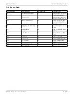
Miscellaneous setting page

•  Shutdown Delay Min: UPS will shut down in setting minutes. The countdown will start after 

confirming the pop-up screen. 

•  Restore Delay Min: UPS will automatically restart in setting minutes after the UPS shuts down. 

•  New Password: Set up User new password to enter “ADVANCE User” menu page.

•  DefaultUserPassword:


YES: After “YES” is set, User password will restore default setting value.


NO: After “NO” is set, the UPS will cancel this operation. 

Содержание E91

Страница 1: ...E91 Online UPS 10kVA 15kVA 20kVA 30kVA 40kVA Models User Installation Manual www xpcc com 2022 Xtreme Power Conversion Corporation All rights reserved Rev 3 25 22...

Страница 2: ...G AND INSPECTION 6 2 2 UPS FLOOR ANCHORING 6 2 3 WIRING TERMINAL VIEW 7 2 4 OPERATION PRINCIPLE 9 2 5 SINGLEUPSINSTALLATION 9 2 6 UPSINSTALLATIONFORPARALLELSYSTEM 12 2 7 SOFTWARE INSTALLATION 14 3 OPE...

Страница 3: ...heat source Do not block ventilation holes on the UPS housing 1 3 Installation Do not connect appliances or devices which would overload the UPS e g big motor type equipment to the UPS output termina...

Страница 4: ...electrical maintenance personnel of the presence of a UPS in the circuit The label will bear the following or an equivalent text Before working on this circuit Isolate Uninterruptible Power Supply UP...

Страница 5: ...be operated by any individuals with no previous experience 1 6 Standards Safety UL 1778 CSA C22 2 No 107 3 14 EMI Conducted Emission FCC Part 15 Subpart B Class A Radiated Emission FCC Part 15 Subpart...

Страница 6: ...parallel cable option One shared current cable option NOTE Before the installation please inspect the unit Be sure that there is no physical damage to the unit Do not turn on the unit and notify the...

Страница 7: ...poration E91 User s Manual Page 7 Uninterruptible Power Supply 2 3 Wiring Terminal View E91 units with internal batteries E91 10K Rear Panel E91 15K 20K Rear Panel E91 10K Input Output Terminal E91 15...

Страница 8: ...sion Corporation E91 User s Manual Page 8 Uninterruptible Power Supply E91 units with internal batteries E91 30 40K front view door removed E91 30 40K rear view E91 30 40K wiring panels E91 30 40k cab...

Страница 9: ...normal operation To activate EPO function please remove the jumper 4 Share current port 5 Parallel port 6 Intelligent slot 7 External battery connector 8 Line input circuit breaker switch 9 Maintenanc...

Страница 10: ...the mains switch in the building before installation 3 Turn off all the connected devices before connecting to the UPS 4 Prepare wires based on the following table CAUTION To reduce the risk of fire...

Страница 11: ...s Connect the grounding earthing wire first when making other wire connections Re move the grounding earthing wire last when connecting the UPS NOTE For single utility power system connect input termi...

Страница 12: ...40K Battery connection wiring NOTE 1 Make sure that the wires are connected securely with the terminals NOTE 2 Please install the output breaker between the output terminal and the load and the break...

Страница 13: ...onnection with wrong battery voltage may cause irreversible damage of the UPS Pay special attention to the polarity marking on external battery terminal block Connection with wrong battery voltage may...

Страница 14: ...l system for 30K 40K 6 Refer to the following communication wiring diagrams for share current cable and parallel cable connections Diagram 1 Two UPSs in parallel Diagram 2 Three UPS in parallel Parall...

Страница 15: ...s the button to set up the power supply for the UPS UPS will enter to power on mode After initialization UPS will enter to No Output mode 3 2 LED Indicators and LCD Panel LED Indicators There are 4 LE...

Страница 16: ...WORD INSTALL INFO VOL CALI CURR CALI INITIAL ELECTRICAL BATTERY MISCELLANEOUS UPS SELFTEST ELECTRICAL BATTERY MISCELLANEOUS PAS SWORD 0000 PARAMETER INFO RATED INFO BASIC INFO ADVANCE SAVE SETTING Use...

Страница 17: ...the icon to enter control sub menu D ATALO G I N FO SETTI N G M EASU R E C O N TR O L H O M E 20KVA Bypass M ode 19 52 36 2018 11 07 O N O FF U PS BATT TEST M U TE ALL O N O FF C H AR G ER Touch icon...

Страница 18: ...trol sub menu D ATALO G I N FO SETTI N G M EASU R E C O N TR O L H O M E 20KVA Bypass M ode 19 52 36 2018 11 07 O N O FF U PS BATT TEST M U TE ALL O N O FF C H AR G ER Touch icon to return back to mai...

Страница 19: ...attery testing during battery test period After few seconds battery test result will show on the screen Touch Back to return to main screen immediately or No to cancel this operation and back to main...

Страница 20: ...L screen D ATALO G I N FO SETTI N G M EASU R E C O N TR O L H O M E 20KVA Bypass M ode 19 52 36 2018 11 07 O N O FF U PS BATT TEST M U TE ALL O N O FF C H AR G ER Tur n O n C har ger YES N O D ATALO G...

Страница 21: ...U S N VO L C H AR G C U R R D I SC H G C U R R TEM P R 125 0V 231 3V 229 5V 3 9A 0 0A 27 46VA 46VA 46VA 0 0 0 TO TAL VA O U TPU T W O U TPU T VA R S T 0 0 BATT N VO L TEM P S TEM P T 27 27 Measure scr...

Страница 22: ...back to previous menu NOTE Not all settings are available in every operation mode If the setting is not available in present mode the LCD will keep its original setting parameter showed instead of cha...

Страница 23: ...Xtreme Power Conversion Corporation E91 User s Manual Page 23 Uninterruptible Power Supply The authority list...

Страница 24: ...month and date are set Language Set the LCD language Only English is available Input Source Select the input source There are two options Line utility and generator Line is default setting This settin...

Страница 25: ...e can be done only in Line mode and ECO mode Enable UPS will transfer between line mode and eco mode as needed Disable UPS will remain in programmed mode Disable is the default setting ADVANCE D ATALO...

Страница 26: ...e two options 120V and 127V 120Vac is default setting Output Frequency Select output rated frequency 50Hz The output frequency is setting for 50Hz 60Hz The output frequency is setting for 60Hz 60Hz is...

Страница 27: ...ge range L Low voltage point for bypass The setting range is 96V 110V 96V is default setting H High voltage point for bypass The setting range is 130V 146V 146V is default setting Bypass FRE Range Set...

Страница 28: ...Shutdown Voltage setting Shutdown Voltage If battery voltage is lower than this point in battery mode UPS will automatically shut down The setting range is 10 0V 12 0V 10 7V is default setting The se...

Страница 29: ...N TR O L H O M E 20KVA Bypass M ode 19 52 36 2018 11 07 ELEC TR O N I C BATT M I SC ELLAN EO U S U PS SELFTEST Advance Maintainer Setting Menu Page2 To access the Advance Maintainer Setting menu page...

Страница 30: ...charge current is listed below One charger board There are four options 1A 2A 3A 4A 4A is default setting Two charger boards There are two options 4A and 8A 4A is default setting Three charger boards...

Страница 31: ...E CONTROL HOME 20KVA StanbyMode 19 52 36 2018 11 07 SYS PARAMETER INSTALL INFO VOL CALI CURR CALI 2018 1 SYS Install Date INITIAL BAT Install Date 2018 1 1 1 Install info Page SYS Install Date Set the...

Страница 32: ...tter it s pressing up or down key Press up key to increase 0 1 and press down key to decrease 0 1 Press OK key to confirm the modification Output VOL Output voltage calibration Each click is 0 1 no ma...

Страница 33: ...atter it s pressing up or down key Press up key to increase 0 1 and press down key to decrease 0 1 Press OK key to confirm the modification INITIAL DATALOG INFO SETTING MEASURE CONTROL HOME 20KVA Stan...

Страница 34: ...ial the Parameters YES NO INITIAL PARAMETERS Page PARAMETERS After pressing the confirmation window it will pop up as shown in above screen Touch YES to restore default value Touch Back or No to cance...

Страница 35: ...ear all setting value in EEPROM Touch Back or No to cancel this operation and back to INITIAL menu page Initial Touch PAGE TOUCH CALI After pressing the confirmation window it will pop up as shown in...

Страница 36: ...EC O VO L R ange EC O FR E R ange 146V 64 0H z 56 0H z 115V 125V 58H z 62H z U PS SELFTEST Electrical Setting Page 2 Bypass at UPS off Select the bypass status when manually turning off the UPS This...

Страница 37: ...in battery mode UPS will automatically shut down The setting range is 10 0V 12 0V 10 7V is default setting The setting is only available for long run model Battery Parameter Battery AH setting batter...

Страница 38: ...dvance screen and enter Maintainer password It will show UPS SELFTEST selection in the screen In the screen all tested items are shown unknown Simply click UPS SELFTEST button the UPS will start self...

Страница 39: ...I nst al l D at e PAR St at e PAR I D 2018 2018 Si ngl e 1 I nput Sour ce Al l M ut e M ode M ut e 01 Li ne D i sabl e D i sabl e 01 01 01 Basic Information Page2 SYS Install Date The date of system...

Страница 40: ...z 80V 96V EC O VO L R ange EC O FR E R ange 56 0H z 115V 58 0H z 156V 64 0H z 146V 64 0H z 125V 62 0H z Parameter Information Page 1 Parameter Information Line Voltage Range The acceptable line input...

Страница 41: ...R est or e D el ay 0m i n 0m i n Parameter Information Page 3 Charger Number The information of charger number Max Charge CURR The setting value of the maximum charging current Float VOL The setting v...

Страница 42: ...battery pack to ON position this step only necessary for long run model Then set the line input breaker to ON position At the same time the fan will start running and the UPS will start initializatio...

Страница 43: ...he UPS will enter fault status At this time if bypass is enabled the UPS will power to the load via bypass If bypass function is disabled or the input power is not within bypass acceptable range it wi...

Страница 44: ...in warning status 1 When LCD screen shows Fault Mode and the buzzer beeps once every second it indicates that there are problems for UPS operation Users can read the warning message s from DATA LOG m...

Страница 45: ...output voltage between two UPSs for the same phase to make sure the phase sequence is correct If these two voltage differences are near to zero that means all connections are met Otherwise please chec...

Страница 46: ...then turn off the system All UPSs will transfer to Bypass mode Remove all the maintenance bypass covers and set the maintenance switches from UPS to BPS position Turn off all the input breakers and ba...

Страница 47: ...mal None 17 Inverter R S output line to line short circuited None 67 Bypass O P short circuited None 18 Inverter S T output line to line short circuited None 68 Bypass O P line to line short circuited...

Страница 48: ...situations are dif ferent in parallel system 04 IP phase abnormal 33 Locked in bypass after overload 3 times in 30 minutes 05 Bypass phase abnormal 34 Converter current unbal anced 07 Over charge 3A C...

Страница 49: ...rom UPS out put first Then shut down the UPS and restart it Fault code is shown as 43 UPS is overload too long and be comes fault Then UPS shut down automatically Remove excess loads from UPS output a...

Страница 50: ...rom the batteries Verify that no voltage between the battery terminals and the ground is present before maintenance or repair In this product the battery circuit is not isolated from the input voltage...

Страница 51: ...9 x 26 3 x 32 3 11 9 x 34 x 40 2 23 6 x 31 1 x 65 4 Weight 315 lbs 504 lbs 510 lbs 690 lbs 831 lbs OPTIONAL BATTERY PACK Model EBP09 2 EBP09 5 EBP10 5 Battery quantity and size 40 12V 9AH 100 12V 9AH...

Страница 52: ...sk you for the above information and if possible help solve your problem over the phone In the event that the unit requires factory service the technician will issue you a Return Mate rial Authorizati...

Страница 53: ...approved third party b the equipment is damaged by the customer is improperly used or stored is subjected to an adverse operating environment or is operated outside the limits of its electrical specif...

Отзывы: