background image

VESDA-E VEP-A10-P Product Guide

80

www.xtralis.com

7.5

Replacing the Aspirator

Caution:

Electrostatic discharge (ESD) precautions need to be taken prior to removing the fascia from
the detector. A wrist strap must be connected to the case of the detector (Figure 1-1).

Attention :

Les precausions contre le decharge electrostatique dois etre respecter avant d’ouvrir le panneau
du detecteur. Un bracelet doit être raccordé au panneau du détecteur (Figure 7-7).

Ensure the area surrounding the aspirator is clear of dirt and debris prior to replacement.

Care must be taken during aspirator replacement. The aspirator must be correctly seated; it is essential to
ensure that the gaskets are not damaged or dislodged from the underside of the aspirator.

Remove the Aspirator

1. Turn off the 24V DC power to the detector.
2. Open the front door and remove the front fascia. Refer to Sections 7.2 and 1.1 for further information.
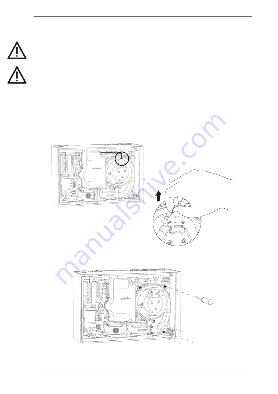
3. Disconnect the aspirator cable (A) (Figure 7-10).

A

Figure 7-10: Disconnect the aspirator cable

4. Remove the six screws holding the aspirator to the detector base (Figure 7-11).

Figure 7-11: Remove aspirator mounting screws

5. Remove the aspirator perpendicular to the detector body (Figure 7-12).

Содержание VESDA-E VEP-A10-P

Страница 1: ...VEP A10 P 4 Pipes VESDA E VEP A10 P Product Guide September 2020 Doc No 22071_15 Part No AD30311 000 ...

Страница 2: ......

Страница 3: ...e Xtralis is not responsible and cannot be held accountable for any liability that may arise due to improper use of the equipment and or failure to take proper precautions Only persons trained through an Xtralis accredited training course can install test and maintain the system Liability You agree to install configure and use the products strictly in accordance with the User Manual and product do...

Страница 4: ...his document Convention Description Bold Used to denote emphasis Used for names of menus menu options toolbar buttons Italics Used to denote references to other parts of this document or other documents Used for the result of an action The following icons are used in this document Convention Description Caution This icon is used to indicate that there is a danger to equipment The danger could be l...

Страница 5: ...en the equipment and receiver connect the equipment to a power outlet which is on a different power circuit to the receiver or consult the dealer or an experienced radio television technician for help FDA This Xtralis product incorporates a laser device and is classified as a Class 1 laser product that complies with FDA regulations 21 CFR 1040 10 The laser is housed in a sealed detector chamber an...

Страница 6: ... transport time less than 110 seconds These limits should be verified using ASPIRE during the design of the sampling pipe network The product is compliant with EN 54 20 flow monitoring requirements provided the following conditions are met l The minor low and minor high flow thresholds should be set at 85 and 115 respectively l The flow through the detector predicted by ASPIRE must be greater than...

Страница 7: ...iew l WPA 2 encryption must be used whenever Wi Fi is enabled l Restrict access to HLI devices to authorized personnel only l Passwords must be chosen in line with the guidelines in the detector user guide and provided to trusted users only l Default PIN codes must be changed as part of the initial configuration System Maintenance Requirements l Do NOT use the USB port for long term monitoring or ...

Страница 8: ...VESDA E VEP A10 P Product Guide vi www xtralis com This page is intentionally left blank ...

Страница 9: ...System Check 45 5 Configuration 47 5 1 Communication between Xtralis VSC and the detector 47 5 2 Connecting to the Detector 51 5 3 Security 53 5 4 Commands 54 5 5 Configuration Options 57 5 6 Factory Default Settings 68 6 Commissioning 71 6 1 AutoLearn Smoke 71 6 2 AutoLearn Flow 72 6 3 Commissioning Smoke Test 72 7 Maintenance 73 7 1 Standby 73 7 2 Open the Door 74 7 3 Replacing the Filter 75 7 4...

Страница 10: ...VESDA E VEP A10 P Product Guide 2 www xtralis com A 3 Smoke Test 97 A 4 Air Sampling Test Results 97 B Glossary 99 Index 101 ...

Страница 11: ...ance l Wide sensitivity range l Flow fault thresholds configurable per port l Long life easy to replace air sample filter l 3 5 colour touch screen for status review l Quiet operation l Advanced remote diagnostics l Area coverage l up to 2 000 m 21 520 ft VEP A10 P l Up to four inlet pipes l Total maximum pipe length l Four pipe VEP A10 P 560 m 1 837 ft l Referencing l AutoLearn Smoke and Flow l S...

Страница 12: ...VESDA E VEP A10 P Product Guide 4 www xtralis com This page is intentionally left blank ...

Страница 13: ... the optical surfaces inside the detection chamber from contamination The detection chamber uses a short wavelength laser light source in conjunction with photodiodes and advanced imaging technology to achieve optimum response to a wide range of smoke types If the detected smoke is higher than the set alarm thresholds it is reported as an Alert Action Fire 1 or Fire 2 alarm condition Air is exhaus...

Страница 14: ...ED is lit when the Alert threshold is reached The LED will flash once per second until the condition is acknowledged Disabled The DISABLED LED is lit continuously when the detector is disabled and flashes once every two seconds when the detector is in Standby mode Fault The FAULT LED is lit when a fault condition is detected The LED will flash once per second until the condition is acknowledged Re...

Страница 15: ...he button will not operate if l the detector is disabled through the GPI function or l the RESET DISABLE button has been configured as locked out Refer to section 5 5 8 for further information 2 3 3 Touch Screen The built in 3 5 touch screen provides a range of status information accessible via a series of screens Main Screen The Main Screen displays a set of important information concerning the d...

Страница 16: ...o normalize the detector press and hold the button until the AutoConfig LED illuminates continuously approximately 2 seconds then release the button l To initiate AutoLearn Smoke and Flow press and hold the AutoConfig button until the AutoConfig LED starts flashing approximately 15 seconds then release the button l Cancel the AutoLearn or Normalization functions by pressing and holding the AutoCon...

Страница 17: ...network connection between the detector and a PC or laptop installed with Xtralis VSC Refer to Section 4 3 4 for information on connecting the Ethernet lead and Section 5 1 2 for information on creating connection profiles in Xtralis VSC A password is required to access the detector via ethernet connection It is initially set using Xtralis VSC during configuration with the USB port and the user is...

Страница 18: ...t not be exposed to sunlight or other radiation sources Sampling Pipe Network l Maximum length per pipe when using four straight pipes l Four pipe VEP A10 P 70 m 230 ft l Maximum total pipe length with branches l Four pipe VEP A10 P 560 m 1 837 ft l Pipe Modeling Design Tool ASPIRE l Refer to Section 3 1 Design Considerations Note Standards compliance of a particular pipe network must be determine...

Страница 19: ...ttings Referencing Reference smoke level source Table 2 2 VEP A10 P Detector Specifications continued Table 2 3 Key Software Features Event Log Up to 20 000 events stored on FIFO basis AutoLearn l Minimum 15 minutes l Maximum 15 days 23 hrs 59 minutes l Recommended 14 days Thresholds are automatically changed from the previously set values to the updated values after the AutoLearn process has comp...

Страница 20: ... 12 B 35 0 1 38 C 45 0 1 77 D 134 0 5 28 E 34 0 1 34 F 34 0 1 34 G 34 0 1 34 H 34 0 1 34 I 26 5 1 04 J 350 0 13 78 K 224 0 8 82 L 230 2 9 06 M 135 5 5 3 N 132 3 5 21 O 28 5 1 12 P 35 0 1 38 Q 45 0 1 77 R 127 0 5 0 S 143 0 5 63 T 26 0 1 02 Figure 2 9 Front top bottom and side dimensions 12 www xtralis com ...

Страница 21: ...A B C D E F mm inch A 17 5 0 69 B 315 0 12 4 C 17 5 0 69 D 144 99 5 71 E 77 2 3 04 F 3 5 0 1 Figure 2 10 Rear dimensions with Mounting Bracket VESDA E VEP A10 P Product Guide www xtralis com 13 ...

Страница 22: ...duct Guide A B C D E F G H mm inch A 224 0 8 82 B 112 0 4 41 C 40 9 1 61 D 268 39 10 57 E 40 71 1 6 F 20 25 0 8 G 183 5 7 22 H 20 25 0 8 Figure 2 11 Rear Dimensions with hole locations for direct mounting 14 www xtralis com ...

Страница 23: ...he pipe l Pipe ends must be made smooth for bonding l Sampling holes must be drilled in line and perpendicular to the pipe l Sampling holes must be clear of rough edges and debris l Pipes are free of debris l All joints must be bonded except the end caps and pipes entering the detector Notes l Sampling holes should be angled between 30 and 45 into the direction of airflow or point downwards in sta...

Страница 24: ...he detector via the exhaust port at the bottom of the unit enclosure The air exhaust port is tapered to accommodate standard pipes of OD 25 mm ID 21 mm and to provide an airtight seal IPS inch pipes 1 05 inch OD require an adaptor VSP 961 as shown in Figure 3 2 If required connect an outlet pipe to the exhaust manifold DO NOT glue this pipe to the exhaust manifold as this will void the warranty Fi...

Страница 25: ...xtralis com l A 24 VDC Power Supply and backup battery compliant with local fire protection codes and standards l Screws and inserts for the mounting bracket that are appropriate for the installation location l Type A to Type B USB Interface Lead required for initial configuration of the detector Figure 4 1 l Wrist strap for ESD prevention Figure 4 1 Type A to Type B USB Interface Lead 4 1 Prepare...

Страница 26: ...r Figure 4 4 noting the location of air sampling pipes and cable entry points Due to the rigid nature of the plastic pipe installation must provide for sufficient movement in all pipework air inlet air exhaust and cable pipes to allow pipe ends to be easily fitted and removed A B Legend A Min 50 mm 2 in below ceiling level B Mounting Bracket The detector can be mounted directly against a wall or o...

Страница 27: ...e user interface has the correct orientation The door must be moved to the other side of the fascia to allow access to the electrical sockets and filter This is done as follows 1 Place the detector on a flat surface with the back plate facing down 2 Open the front door and remove the fascia Refer to Sections 7 2 on page 74 and 7 4 on page 78 for further information Figure 4 5 Detector with fascia ...

Страница 28: ...ure 4 6 Tabs used to remove top and bottom cover Legend A Top cover retaining tabs B Bottom cover retaining tabs 4 Detach the tethers Figure 4 7 and Figure 4 8 You can leave the cables from the detector to the fascia connected Figure 4 7 Detaching the tethers ...

Страница 29: ...A10 P Product Guide www xtralis com 21 Figure 4 8 Detector with tethers detached 5 Detach the front door from the fascia by removing pin A from the hinge Figure 4 9 Figure 4 10 Leave pin B in place do not remove it ...

Страница 30: ...VESDA E VEP A10 P Product Guide 22 www xtralis com B A Figure 4 9 Removing door hinge pin A Figure 4 10 Detaching door ...

Страница 31: ...by doing the following a Leave the fascia upright b Rotate the detector 180 degrees c Rotate the door 180 degrees and place it next to the right side of the fascia 7 Replace the door hinge pin Figure 4 12 Figure 4 13 A 180 o B Figure 4 11 Rotate detector and door and move door to right side of fascia ...

Страница 32: ...VESDA E VEP A10 P Product Guide 24 www xtralis com Figure 4 12 Replacing the door hinge pin showing correct positioning of door and pin ...

Страница 33: ...he door hinge pin Figure 4 14 Correct positioning of door hinge pin when fully in place 8 Re attach the tethers Attach at the slots circled in Figure 4 15 Position the tethers in the slots and pull up as shown in Figure 4 16 Figure 4 15 Re attach tethers at circled positions ...

Страница 34: ...overs 10 Re attach the fascia Re attach to the front of the detector by tightening the two retaining screws as shown in Figure 7 8 11 The detector is now inverted The display should be upright while the exhaust vent is at the top and sampling pipe inlets at the bottom The electrical connections and filter should be accessible by opening the door ...

Страница 35: ...with the bottom depth line F E F B D A C D Legend A Mounting bracket B Sampling Pipes C Electrical Conduit D Pipe alignment marks E 3 4 inch IPS pipe 1 05 inch OD depth F 25 mm pipe depth Figure 4 17 Position Mounting Bracket in line with pipes 2 Mark the mounting surface through two keyholes B on the mounting surface Figure 4 18 A B B Legend A Mounting bracket B Keyholes Figure 4 18 Mark keyholes...

Страница 36: ... slots on the mounting bracket and slide the detector down until the top of the detector is flush with the top of the mounting bracket Figure 4 21 A A A Legend A Mounting buttons Figure 4 21 Mounting the detector 7 Open the door on the front of the detector Figure 4 22 Refer to Section 7 2 on page 74 for further information on how to open the door 8 Insert and tighten the locking screw A This secu...

Страница 37: ...nting template 3 Insert two M4 button head screws at positions A and B such that the screw head is protruding 7 mm from the wall Figure 4 24 Drill a pilot hole at position C for later insertion of a screw at Step 12 7mm Upright Detector Inverted Detector 25mm 3 4 IPS 25mm 3 4 IPS Edge of Detector 25m m 3 4 IPS 25m m 3 4 IPS Edge of Dete ctor B A A B C C Figure 4 24 Insert mounting screws 4 Positio...

Страница 38: ...ed retract the inlet and exhaust pipes and electrical conduit 10 Mount the detector onto the screws using the keyholes using the following steps Upright Detector Inverted Detector Figure 4 26 Mount the detector l Position the right keyhole on the rear of the detector over the head of the right screw A Figure 4 27 A A Upright Detector Inverted Detector Figure 4 27 Position detector over screw l Sli...

Страница 39: ...head of screw B Push the detector to the wall Figure 4 29 B B Upright Detector Inverted Detector Figure 4 29 Position detector on the second screw l Rotate the detector anticlockwise or clockwise for an inverted detector to lock the detector on to the screw Figure 4 30 Upright Detector Inverted Detector Figure 4 30 Rotate the detector 12 Insert an M4 screw at the small end of the detector s bottom...

Страница 40: ...VESDA E VEP A10 P Product Guide 32 www xtralis com Upright Detector Inverted Detector Figure 4 31 Locking screw 13 Tighten the top and bottom screws 14 Insert the pipes and electrical conduit ...

Страница 41: ...is not UL tested Caution Electrostatic discharge ESD precautions need to be taken prior to removing the fascia from the detector in order to prevent damage to sensitive electronic components within the VEP A10 P Attention Les precausions contre le decharge electrostatique dois etre respecter avant d ouvrir le panneau du detecteur afin de prevenir au dommage des composants electroniques a l interie...

Страница 42: ...o sets of power terminals on the main board Figure 4 33 Connect a 24 VDC power supply which is compliant with local fire protection codes and standards to the PWR IN socket and if required loop out to another detector via the PWR OUT socket The detector will not operate if the power supply polarity is reversed Caution Operating the detector when DC supply voltage is outside the specified voltage r...

Страница 43: ... to the PC or Laptop This ensures that the required USB drivers are present Notes l The USB port must not be used for permanent field connection For example do not use a USB to Ethernet adaptor to connect the detector to a LAN using USB l Refer to the Xtralis VSC documentation for operating system compatibility information Ethernet The Ethernet port is used for permanent network connection to the ...

Страница 44: ...ample closed loop VESDAnet network The VESDA E VEP A10 P detector is shipped with the VESDAnet A and B terminals looped Remove the A and B links prior to connecting the detector to the VESDAnet If the detector is not to be networked with other devices then do not remove the A and B links Figure 4 36 Closed loop for standalone detectors with VESDAnet capability Note Refer to the VESDA E Communicati...

Страница 45: ...ay Operation URGENT FAULT Relay All Other Relays No Fault Energized Fault or unpowered state No Fire De energized Fire Relay Assignments and Behaviour l Relays 1 2 4 5 and 7 are fully configurable For example Relay 5 could be configured to de energize on Alert l Relays 3 and 6 are fixed to Urgent Fault and Fire 1 respectively These relays may be assigned additional conditions Relay Default Assignm...

Страница 46: ...iguration Configurability 5 Action No Energizes when the Action alarm is initiated Fully configurable 6 Fire 1 No Energizes when the Fire 1 alarm is initiated Fire 1 cannot be removed Other conditions can be added 7 Fire 2 No Energizes when the Fire 2 alarm is initiated Fully configurable Table 4 2 Default Relay Assignments continued ...

Страница 47: ... 2V signals GPI OFF The input is isolated from the system by an opto coupler device 4 3 8 Monitored General Purpose Input GPI Wiring The monitored GPI senses contact closure and is configurable to initiate the same actions as the unmonitored GPI Remote Reset is the default setting A closed contact signals GPI ON and open contact signals GPI OFF A 10K end of line resistor is used to allow the detec...

Страница 48: ...ing details of the third party equipment Normally Closed NC Normally Open NO Normally Open NO Normally Closed NC Normally Open NO Fire Input EOL Normal Short Fire Open Wiring Fault EOL Normal Short Fire Fault Input EOL Normal EOL EOL EOL NC NO Monitored GPI Set to Mains OK PSU 5 30VDC NC NO This shows normal operation no fault EOL Relay shown energized which is the no fault condition EOL Normal Op...

Страница 49: ...VESDA E VEP A10 P Product Guide www xtralis com 41 Legend A External device 1 to N B End of Line Resistor at device end of wiring C GPI Pin 1 D GPI Pin 2 Figure 4 39 Power Supply Connection Diagram ...

Страница 50: ...h age l expected temperature variations Note It is recommended that batteries be inspected and changed as per manufacturer s specifications or as per local codes and standards To facilitate the calculation of the backup battery size a Battery Calculation Sheet is included below Equipment Normal loads 24 V DC Backlight off Full alarm load 24 V DC Backlight on Load A Qty Total Load A Qty Total Detec...

Страница 51: ...inals and that the polarity is correct On power up l The Power LED illuminates and the detector runs a series of self diagnostic tests l If there is a fault the Fault LED illuminates To identify the fault check the Active Event List for the detector using Xtralis VSC l The aspirator starts up and air may be felt flowing out of the exhaust port It is normal for the detector to display airflow fault...

Страница 52: ...urther information The sampling air pipes are firmly connected to the air inlet ports Ensure that the pipes are NOT glued The power supply wiring has been connected to the detector If required the end of line resistor for the monitored GPI has been connected Refer to Section 4 3 11 on page 40 for further information The alarm and fault relay output terminals of the detector have been connected to ...

Страница 53: ...lling the VEP A10 P detector before it is commissioned for use To perform the preliminary system check l Power up the detector by connecting the power supply to the Power In terminal l Check that the display is functioning l Check that the aspirator is functioning by determining whether air is being expelled from the exhaust port ...

Страница 54: ...VESDA E VEP A10 P Product Guide 46 www xtralis com This page is intentionally left blank ...

Страница 55: ...e authentication password l create a connection profile for Ethernet as required l connect to the detector USB is used for initial configuration however it must not be used for permanent connection Permanent connection for secondary monitoring must only be done with Ethernet For example the installer would connect directly to a VEP A10 P using the USB port with a laptop running Xtralis VSC in orde...

Страница 56: ...e 5 1 Connection Manager 2 Select Add The Add Connection dialog is displayed Figure 5 2 Figure 5 2 Add Connection 3 Select the VESDAnet connection option then select Next Adding a USB Connection 1 Select USB then select Next Figure 5 3 Figure 5 3 Select USB ...

Страница 57: ...thernet then select Next Figure 5 5 Figure 5 5 Select Ethernet 2 Enter the IP address of the detector Enter the password that has been set for Ethernet authentication Select Next Figure 5 6 Note The IP address and password of the detector is configured in the Ethernet options section during initial setup with a USB connection Refer to Section 5 5 3 on page 58 or 1 0 1 on page 1 for further informa...

Страница 58: ...VESDA E VEP A10 P Product Guide 50 www xtralis com 3 Enter a unique name for the Connection or accept the pre generated name then select Finish Figure 5 7 Figure 5 7 Enter a Connection Name ...

Страница 59: ...tor and the PC installed with Xtralis VSC can be made using a router or switch Figure 5 9 or directly between the two devices Complex networks are beyond the scope of this document For a successful connection Ethernet connectivity must be enabled within the detector the detector must have an IP address and an authentication password must be set Configuration procedures for these requirements are d...

Страница 60: ...n be accessed via another VESDA E device acting as a gateway l the VEP A10 P must be physically connected to the VESDAnet as described in Section 1 0 1 l another VESDA E detector can be used as a gateway to communicate between the PC with Xtralis VSC and any device connected to the VESDAnet C A D D D Legend A PC or Laptop installed with Xtralis VSC B Router or access point C VEP A10 P used as a ga...

Страница 61: ...via Xtralis VSC user functionality is initially limited For additional privileges the user must log in to the detector using an 4 digit numeric PIN code In Xtralis VSC select Logon from the Connection menu and enter the PIN User Level Access Level Functional Authorization USR Low This is the USER or the OPERATOR level The user can view the event log and change the date and time They can also perfo...

Страница 62: ...End Standby command causes the detector to exit Standby mode Reset The Reset command unlatches all latched alarms and faults and returns relays to their normal state Clears the Xtralis VSC active event list Reset does not enable a disabled detector or reactivate a detector that is in Standby mode Start Normalize Air Flow Starts the air flow normalization process for the selected detector The norma...

Страница 63: ...for 5 seconds The LED will turn off Start AutoLearn Smoke In Xtralis VSC you will be prompted to set the period of time that the environment is monitored to allow the system to decide what smoke thresholds are most appropriate When the AutoLearn has finished the smoke thresholds are overwritten After AutoLearn is complete review to confirm that the thresholds are within ranges allowed by local cod...

Страница 64: ...onditions to occur Alarm relays will energize unless the detector is disabled Start Air Flow Fault Test Tests the air flow sensing system by shutting down the aspirator Start Relay Test Tests the available relays by activating and deactivating as required Start LED Test Tests each LED by cycling through all LEDs on the detector display panel Return to Factory Defaults Restores the configuration of...

Страница 65: ...tion of the physical location of the detector This name will appear on Xtralis VSC and on the LCD display of the A10 model detector l Serial Number The serial number of the device This is factory set and cannot be changed l VESDA Zone The unique zone number used to link this detector and remote display relay devices or remote relay which output alarm and trouble status for this detector to the Fir...

Страница 66: ...option should normally not be checked l Minimum interval between status events The minimum time interval between status updates for the selected detector 5 5 3 Ethernet Options The Ethernet options provide the ability to configure the detector to join an existing wired Ethernet network using the normal building network connection process or be directly connected to a PC or laptop Figure 5 13 Ether...

Страница 67: ...lows direct connection between a PC or Laptop and the VEP A10 P using a standard Ethernet lead l Prior to connecting the detector to a router or other gateway device the default address must be changed to an address in the range used by the router This can be done by connecting to the detector using the USB port l Subnet Mask The subnet mask for the network l Default Gateway The IP address of the ...

Страница 68: ...ked the delay timer for each alarm condition will not start until both the smoke level has exceeded the threshold and the delay timer for the previous alarm condition has expired If not checked the delay timer for each alarm condition will start immediately when the smoke level exceeds the threshold l Instant Fire If checked the Fire 1 time delay is ignored when the smoke exceeds the Fire 1 thresh...

Страница 69: ... set closer to their limits l Major High The level of air flow considered to be so far above normal as to require urgent attention l Minor High The level of air flow considered to be above normal but not urgent l Minor Low The level of air flow considered to be below normal but not urgent l Major Low The level of air flow considered to be so far below normal as to require urgent attention l Signif...

Страница 70: ...oduct Guide 62 www xtralis com Figure 5 16 Filter Options Service Interval days The time period after a new filter is installed at which non urgent fault Filter smoke dust limit nearly exceeded Fault 767 will be generated ...

Страница 71: ...of the VEP A10 P detector monitoring the protected area is limited to 50 of the Fire 1 alarm threshold of the VEP A10 P A single reference detector can be used by multiple VESDA detectors within the protected area The percentage of reference smoke level subtracted can be set differently for each detector monitoring the protected area This is set using the dilution factor parameter There may be a t...

Страница 72: ...e Input Options The configuration options are as follows l GPI function Unmonitored and GPI function Monitored Refer to Table 5 3 below for a description of the individual selections l Button Lockout If the checkbox is ticked the Reset Disable and Acknowledge functions can t be executed using the front panel button Function State Change External Reset Unmonitored GPI The detector resets on a 0 VDC...

Страница 73: ...nitored GPI l The detector is held in Standby mode see Section 7 1 while 5 VDC l The detector exits Standby mode at a 5 VDC to 0 VDC falling edge Monitored GPI l The detector is held Standby mode see Section 7 1 while contact is closed l The detector exits Standby mode when the contact opens Note No alarms can be generated while the detector is in standby mode 0V 5V Standby Open Closed Enabled Sta...

Страница 74: ...closure or opening of the contact and l The detector is held disabled while contact is closed l The detector is enabled when the contact opens 0V 5V Reset and enabled Disabled Reset Open Closed Disabled Reset Reset and enabled Inverted Reset Unmonitored GPI l The detector resets on a 5 VDC to 0 VDC falling edge Monitored GPI l The detector resets on the opening of the contact 0V 5V Reset Open Clos...

Страница 75: ...y Energized row l If checked the relay is set Normally Energized l If unchecked the relay is set Normally De energized In the Normally De energized mode no drive is applied to the relay coil until the assigned condition such as Alert or Fire 1 occurs The Normally Energized mode is the opposite Drive is removed from the relay coil when the condition occurs The default mode of the relays is listed i...

Страница 76: ...obs ft 0 005 obs m 0 0016 obs ft 2 0 obs m 0 625 obs ft Yes Action 0 14 obs m 0 044 obs ft 0 005 obs m 0 0016 obs ft 2 0 obs m 0 625 obs ft Yes Fire 1 0 20 obs m 0 0063 obs ft 0 010 obs m 0 0031 obs ft 2 0 obs m 0 625 obs ft Yes Fire 2 2 0 obs m 0 625 obs ft 0 02 obs m 0 0063 obs ft 20 0 obs m 6 25 obs ft Yes Delays 10 seconds 0 seconds 60 seconds Yes Cumulative Delay Unchecked Unchecked Checked Y...

Страница 77: ...Referencing Referencing Enabled Unchecked Unchecked Checked Yes Detector Blank Zone 1 Zone 254 Yes Delay 2 minutes 0 minutes 15 minutes Yes Dilution Factor 100 1 100 Yes General Purpose Inputs GPI Function Unmonitored Reset n a n a Yes GPI Function Monitored Mains OK n a n a Yes Button Lockout Unchecked Unchecked Checked Yes Relays Assignment of Relays to conditions See Table 4 2 n a n a Yes Norma...

Страница 78: ...VESDA E VEP A10 P Product Guide 70 www xtralis com This page is intentionally left blank ...

Страница 79: ...ng without faults providing the flow rates are maintained as indicated in Section 3 1 It is important that the protected environment is working under normal operating conditions when operating the AutoLearn processes Xtralis recommends that a 14 day period is used After AutoLearn is complete review to confirm that the thresholds are within the range allowed by local codes and standards For code sp...

Страница 80: ...iations During the learning cycle if a flow fault is reached AutoLearn will not complete its cycle In this situation the user must restart the AutoLearn process If AutoLearn is halted the flow thresholds will be left at the previous settings Conditions experienced during learning are assumed to be representative of normal operating conditions The AutoLearn Flow learning times can be set between 15...

Страница 81: ...evices dependent on the detector are isolated before work commences Attention Pendant que le detecteur ou la zone est desactivee aucun feu d indication va etre emis par le detecteur Avant tout entretien ou tester l Informer les autorité de supervision appropriée l S assurer que tout les appareils auxiliaires dépendants sur le détecteur sont isolés avant de commencer aucun travail 7 1 Standby When ...

Страница 82: ... maintenance functions require that front door be opened Open the Front Door 1 Release the door latch by inserting a thin screwdriver into the hole at the bottom left of the door and firmly pushing perpendicular to the door surface 2 Pull the door open Figure 7 1 Open the door ...

Страница 83: ... high levels of contamination Remove the Filter Note that it is not necessary to turn off the 24V DC power to the detector when removing and replacing the filter The detector will turn off the aspirator when it detects that the filter has been removed and a fault will be signaled 1 Open the front door Ensure that the area around the filter is free of lint and dust before removing the filter Refer ...

Страница 84: ...hich allow it to be tilted on the chamber manifold Figure 7 3 Tilt Filter towards the left hand side of the detector 4 Lift the filter out of the detector case Figure 7 4 Figure 7 4 Remove Filter Reinstall the Filter Note Ensure that the new filter is free of lint and dust 1 Tilt the filter towards the left and position its hinge pins in their recess Figure 7 5 ...

Страница 85: ...ww xtralis com 77 Figure 7 5 Engage hinge pins 3 Tilt the filter to the right 4 Firmly press as shown in Figure 7 6 until the filter makes a distinct clicking sound and no additional movement is possible Figure 7 6 Reinstall the Filter ...

Страница 86: ...moving the fascia from the detector A wrist strap must be connected to the case of the detector Figure 7 7 Attention Les precausions contre le decharge electrostatique dois etre respecter avant d ouvrir le panneau du detecteur Un bracelet doit être raccordé au panneau du détecteur Figure 7 7 Figure 7 7 Wrist Strap application Remove the Fascia 1 Turn off the 24V DC power to the detector 2 Remove t...

Страница 87: ...VESDA E VEP A10 P Product Guide www xtralis com 79 Figure 7 8 Fascia removal remove screws 3 Remove the fascia and allow it to hang by the two tether straps Figure 7 9 Fascia hanging on two tethers ...

Страница 88: ...clear of dirt and debris prior to replacement Care must be taken during aspirator replacement The aspirator must be correctly seated it is essential to ensure that the gaskets are not damaged or dislodged from the underside of the aspirator Remove the Aspirator 1 Turn off the 24V DC power to the detector 2 Open the front door and remove the front fascia Refer to Sections 7 2 and 1 1 for further in...

Страница 89: ...VESDA E VEP A10 P Product Guide www xtralis com 81 Figure 7 12 Remove aspirator from the detector Reinstall the replacement Aspirator To replace the aspirator follow the removal procedure in reverse ...

Страница 90: ... and 1 1 for further information 2 Remove the Sampling Module as described in Section 7 7 on page 86 3 Remove Smoke Detection Chamber as described below 4 Install the new Smoke Detection Chamber as described below 5 Reinstall the Sampling Module as described in Section 7 7 on page 86 Remove the Smoke Detection Chamber 1 Turn off the 24V DC power to the detector 2 Remove the Filter Refer to Section...

Страница 91: ...VESDA E VEP A10 P Product Guide www xtralis com 83 Figure 7 14 Disconnect Chamber Loom 5 Remove the chamber from the detector base Figure 7 15 Figure 7 15 Remove the Chamber from the detector base ...

Страница 92: ...ated loom sections beside the air flow sensing module not on top of it This will ensure that when installing the chamber the looms are not caught between the chamber and the air flow sensing module Looms beside module Air flow sensing module Figure 7 16 Position the gray loom 2 Position the chamber looms A and B as shown in Figure 7 17 A B Figure 7 17 Position the Chamber looms ...

Страница 93: ...n the position shown so that the looms are not caught between the chamber and other parts of the detector Figure 7 18 Install the Chamber 4 Secure the four screws which hold the chamber to the detector base Figure 7 13 5 Reconnect the loom to J3 Figure 7 14 6 Reinstall the Filter Refer to Section 1 1 on page 1 for further information ...

Страница 94: ...rea around the Sampling Module is clear of dirt and debris prior to replacement Care must be taken during Sampling Module replacement The Sampling Module must be correctly seated in order for a correct seal to be established between the Sampling Module and the rest of the detector It is essential to ensure that the rubber seal on the underside of the Sampling Module is correctly in place Removing ...

Страница 95: ... P Product Guide www xtralis com 87 4 Press on the lever on the connector to release the catch Figure 7 20 Figure 7 20 Release the Sampling Module cable 5 Undo the three screws holding the Sampling Module Figure 7 21 ...

Страница 96: ...VESDA E VEP A10 P Product Guide 88 www xtralis com 1 2 3 Figure 7 21 Undo Sampling Module screws ...

Страница 97: ...ule Installing a replacement Sampling Module 1 Firmly press the Sampling Module into the detector in the direction of the arrow shown so that the rubber seal on the Sampling Module is seated on the pipes in the detector Figure 7 23 You will feel the module slide onto the pipes Figure 7 23 Reinstall Sampling Module 2 Tighten the three screws and re connect the Sampling Module cable Figure 7 19 ...

Страница 98: ...replaceable Table 7 2 below provides a complete list of these spare parts and each one s ordering number Table 7 2 Spare Parts Part No Description VSP 960 VESDA E VEP Mounting Bracket VSP 962 VESDA E VEP Filter VSP 963 VESDA E VEP Aspirator VSP 964 VESDA E VEP Chamber Assembly VSP 965 VESDA E VEP Sampling Module ...

Страница 99: ...oftware to further investigate the fault 8 2 Troubleshooting with the Front Panel Display The main screen of the VESDA E VEP A10 P touchscreen display features a range of fault indicators When a fault is generated the respective indicator will illuminate Use Xtralis VSC to further investigate the fault by reviewing the event log Fault Indicator Description General detector fault for example an ele...

Страница 100: ...92 www xtralis com Fault Indicator Description Expansion Module fault for example a Remote Display which has previously been in the same VESDA Zone as the detector is now not found on the VESDAnet Table 8 1 Fault Indicators continued ...

Страница 101: ...te and time of the fault the serial number of the device on which the fault has occurred the zone number fault number and a description of the fault For detailed information about a fault select the fault in the active event list or the event log then press F1 Xtralis VSC will display the cause and troubleshooting information for the selected fault Alternatively select Help VSC Help then select Tr...

Страница 102: ...VESDA E VEP A10 P Product Guide 94 www xtralis com This page is intentionally left blank ...

Страница 103: ...etector s Relay outputs connection to the fire panel using the Xtralis VSC Relay Test command Turn each relay on off individually See below Relay 1 Tested Default assignment Disable Relay 2 Tested Default assignment Minor Fault Relay 3 Tested Default assignment Urgent Fault Relay 4 Tested Default assignment Alert Relay 5 Tested Default assignment Action Relay 6 Tested Default assignment Fire 1 Rel...

Страница 104: ...gnment Alert Relay 5 Tested Default assignment Action Relay 6 Tested Default assignment Fire 1 Relay 7 Tested Default assignment Fire 2 Fire 1 relay connection from Remote Display Relay to fire panel tested using the Xtralis VSC Alarm Test Command for the detector Urgent Fault relay connection from Remote Display Relay to fire panel tested using the Xtralis VSC Alarm Test Command for the detector ...

Страница 105: ...and on the File menu A 2 ASPIRE Data Print the ASPIRE Installation Data Pack IDP in order to record the ASPIRE modeling results for the system A 3 Smoke Test Table A 2 Smoke Test commissioning form Test Results Test Method Type of Smoke Test Date A 4 Air Sampling Test Results Table A 3 Air Sampling Test results commissioning form Pipe 1 Pipe 2 Pipe 3 Pipe 4 Transport Time from End Cap Hole Test 1 ...

Страница 106: ...VESDA E VEP A10 P Product Guide 98 www xtralis com This page is intentionally left blank ...

Страница 107: ...for example alarms troubles user commands which is stored in the detector F Fault An urgent fault is a condition where the system requires urgent attention as it may be unable to detect an alarm condition A minor fault is a condition where the system requires attention or maintenance but is still able to detect an alarm condition Fire Alarm Control Panel FACP A central monitoring and control syste...

Страница 108: ...protected area Relay A device on a detector that has an electrical contact which can be configured to close when a condition occurs such as fire alarm or a fault in the detector This is the primary method used to signal alarms and faults S Sampling Network The pipe network constructed to allow the VESDA E detector to draw air for sampling Sensitivity Sensitivity refers to sensitivity to smoke A hi...

Страница 109: ...ke 55 disable 54 enable 54 normalize air flow 54 rebuild zone list 55 reset 54 return to factory defaults 56 set system date and time 56 standby 54 start air flow fault test 56 start alarm test 56 start AutoLearn flow 55 start AutoLearn smoke 55 start lamp test 56 start major fault test 55 start minor fault test 56 start relay test 56 commissioning 71 95 99 smoke test 72 connection 8 47 add 48 eth...

Страница 110: ...set isolate 64 standby mode 64 unmonitored 3 34 39 40 64 99 use night time threshold 66 H HLI 9 52 99 I isolate 34 37 66 L LED 3 5 6 43 64 73 91 M maintenance 11 check pipe flow 73 check pipe network 73 clean sampling point 73 filter inspection 73 flush pipe network 73 pipe integrity smoke test 73 power supply 73 mounting 10 27 29 44 bracket 17 location 18 locking mechanism 27 orientation 18 screw...

Страница 111: ...0 34 37 40 43 54 64 67 91 99 action 34 alert 34 fault 34 37 fire 34 37 isolate 34 options 67 remote display 9 57 91 reset 5 6 39 43 54 64 66 71 S sampling module 5 86 90 sensitivity 3 10 99 settings 68 default 68 significant smoke change 60 specifications 10 alarm range 10 dimensions 10 power 10 weight 10 standby 54 65 73 75 80 82 supply voltage 10 34 T temperature 10 42 thresholds 5 10 action 6 1...

Страница 112: ...VESDA E VEP A10 P Product Guide 104 www xtralis com Z zone 55 57 73 99 ...

Страница 113: ...erty including but not limited to trademarks copyrights patent are hereby acknowledged You agree not to copy communicate to the public adapt distribute transfer sell modify or publish any contents of this document without the express prior written consent of Xtralis Installation information In order to ensure full functionality refer to the installation instructions as supplied Xtralis ...

Отзывы: