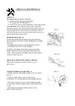
FIG. I
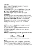
FIG. J
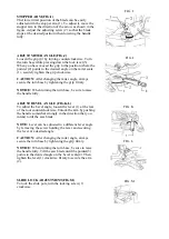
FIG. K
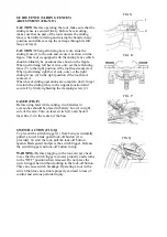
FIG. L
STOPPER ARM (FIG.I)
Thet lower limit position of the blade can be easily
adjusted with the stopper arm (1). To adjust it, move the
stopper arm in the direction of the arrow as shown in the
figure. Adjust the adjusting screw (2) so that the blade
stops at the desired position when lowering the handle
fully.
ADJUST MITER ANGLE(FIG.J)
Loosen the grip (4) by turning counterclockwise. Turn
the turn base while pressing down the lock lever(3).
When you have moved the grip to the position where the
pointer (2) points to the desired angle on the miter scale
(1), securely tighten the grip clockwise.
CAUTION:
After changing the miter angle, always
secure the turn base by tightening the grip firmly.
NOTICE:
When turning the turn base, be sure to raise
the handle fully.
ADJUST BEVEL ANGLE (FIG.K,L)
To adjust the bevel angle, loosen the lever (1) at the rear
of the tool counterclockwise. Unlock the arm by pushing
the handle somewhat strongly in the direction that you
intend to tilt the saw blade.
NOTE:
Lever can be adjusted to a different lever angle
by removing the screw holding the lever and securing
the lever at a desired angle.
CAUTION:
After changing the miter angle, always
secure the turn base by tightening the grip firmly.
NOTICE:
When turning the turn base, be sure to raise
the handle fully. Tilt the saw blade until the pointer(3)
points to the desired angle on the bevel scale(4). Then
tighten the lever(1) clockwise firmly to secure the arm
(2).
SLIDE LOCK ADJUSTMENT(FIG.M)
To lock the slide pole, turn the locking screw (1)
clockwise.
FIG. M
Содержание XT106305
Страница 19: ......


